Simple PWM Stirplate Controller

Homebrew Talk - Beer, Wine, Mead, & Cider Brewing Discussion Forum

Help Support Homebrew Talk - Beer, Wine, Mead, & Cider Brewing Discussion Forum:

This site may earn a commission from merchant affiliate links, including eBay, Amazon, and others.

rocketman768

Supporting Member
HBT Supporter
Joined
Feb 5, 2008
Messages
1,083
Reaction score
28
Location
Evanston, IL
I did a search on the forums, but I can't find a post about a simple PWM controller for stir-plates. I have tested it, and it works great. Any way, here it is:

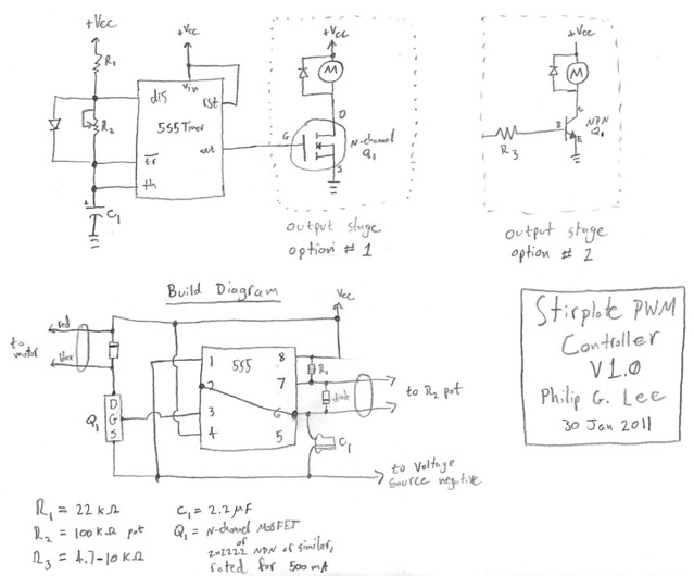
Schematic & Build Diagram
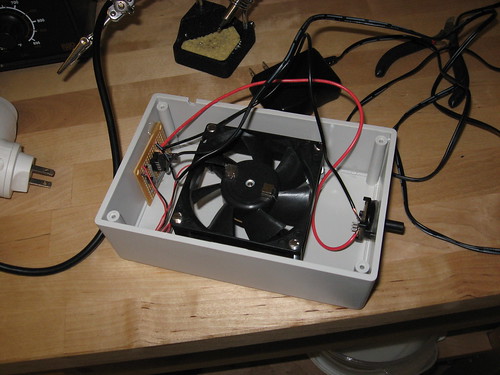
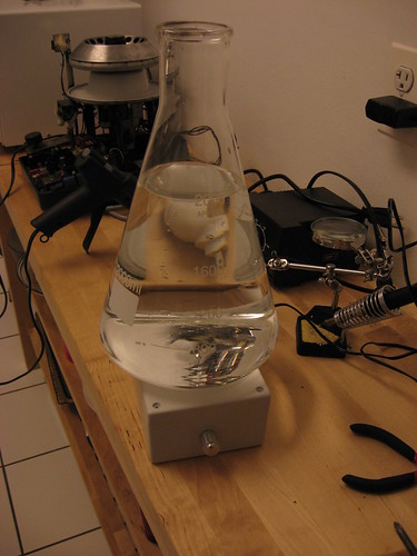
5401944018_890f734d9b_z.jpg


In Action
5399526530_3d055592bc.jpg


5399526536_389e7f72b3.jpg


  • R1 = 22k resistor
  • R2 = 100k pot (use the middle and one of the end pins)
  • R3 = 4.7-10k resistor
  • C1 = 2.2 micro-Farads capacitor
  • Q1 = N-channel MOSFET
All components available at mouser.com (parts list).

The 555 can be a cmos 555 (LMC555) or a regular 555 if you like. Q1 is any standard MOSFET (or NPN transistor, like 2n2222) with a current rating of at least whatever your motor is going to suck (mine draws 100 mA). The diodes are standard silicon diodes. The two wires going the pot are connected to its middle pin, and one of the two end pins (which one determines if turning clockwise increases or decreases speed). I have drawn two options for the output stage. I prefer option 1 because MOSFETS are much more efficient, but they can be hard to find in physical stores.

Make sure your Q1 is oriented in the right way (D,G,S for MOSFET, or C,B,E for NPN) by looking at the data sheet or packaging for the component!

I don't know if there's a discussion about the different speed-control methods, but let me put in my two cents about this design versus others.
Resistor voltage division sucks, because most of the power is being dissipated in the resistors. LM-317 regulators are a bit better, but they still cannot get the motor started at voltages less than about 4V, and the top available voltage is 3V less than the power supply, so you only get a narrow range of workability. PWM is the best I can see, because there is very little energy wasted, and the output is always 0V or Vcc, so you get the necessary torque to spin the motor at low speed, and you can push the motor all the way to full speed.
 
the reason for not finding posts on this is that a simple potentiometer can easily control the speed of a DC fan. I have used PWM for fan control but it is overkill in this application..but hey around here overkill is norm.
 
the reason for not finding posts on this is that a simple potentiometer can easily control the speed of a DC fan. I have used PWM for fan control but it is overkill in this application..but hey around here overkill is norm.

That's what I was talking about when I said resistor voltage division. Until you turn the pot up to about 1/3 or 1/2, the fan won't move. I hate that, because the lower end of the speed range is gone.
 
That's what I was talking about when I said resistor voltage division. Until you turn the pot up to about 1/3 or 1/2, the fan won't move. I hate that, because the lower end of the speed range is gone.

Understood the reason just explaining why so few use this method. The lower end of the speed control isn't going to be that valuable in a stir plate so the loss in the pot doesn't really hurt as most people run them as high as they will go when aerating starters.
 
I don't know if there's a discussion about the different speed-control methods, but let me put in my two cents about this design versus others.
Resistor voltage division sucks, because most of the power is being dissipated in the resistors. LM-317 regulators are a bit better, but they still cannot get the motor started at voltages less than about 4V. PWM is the best I can see, because there is very little energy wasted, and the output is always 0V or 9V, so you get the necessary torque to spin the motor at low speed.

When I saw the title of this thread I thought "Why would you use PWM for your stirplate, that's just overkill!" but this makes a lot of sense... I'm right there with you on being bugged by losing the lower end of the speed range, and it's really not that much more complicated than the other stirplate builds if you have the slightest experience with electronics.

I was planning on starting my stirplate build this weekend, and I think I've got all the parts (except possibly the MOSFET) on hand already. I'll let you know how it goes.
 
Just tested this circuit out and it works great!

The low end of the motor is completely accessible, and it goes all the way to the high end!

However, I had to modify some of the values to suit my motor. I originally planned it to operate at > 20kHz so that you couldn't hear it. However, it appears that the motor I have doesn't do much until you get down around the 100 Hz range. So, I just swapped out the resistors and capacitors as follows:

R1 = 22k
R2 = 100k
C1 = 2.2 micro-F

I'll update this on the OP. The good thing is that now it's operating around 20 Hz, so the only thing you hear out of the motor is a tiny clicking sound, but I expect you won't even hear this when it goes in the box. SWEET.
 
When I saw the title of this thread I thought "Why would you use PWM for your stirplate, that's just overkill!" but this makes a lot of sense... I'm right there with you on being bugged by losing the lower end of the speed range, and it's really not that much more complicated than the other stirplate builds if you have the slightest experience with electronics.

I was planning on starting my stirplate build this weekend, and I think I've got all the parts (except possibly the MOSFET) on hand already. I'll let you know how it goes.

Thanks man. Yeah, it is super simple, especially compared to some other PWMs I was seeing (quad op-amp chips...really?). Also, you can probably use a JFET or even an NPN (if you add a 100 ohm resistor from collector to ground) if you have either of those.
 
Updated the schematic to make it more accessible.

Oh sure, now that I've got it all breadboarded out...

Got it running though, substituted a 2n2222 for the MOSFET as suggested, and it runs nicely. I really appreciate your build diagram, that'll make it much easier when moving to perfboard; the breadboard gets kinda crowded with jumper wires. Shouldn't 4 (reset) be tied to +9v though?

Also, while the 2n2222 worked for a quick test, it got too hot too quick. I'll probably swap out to the MOSFET for the permanent build.
 
Shouldn't 4 (reset) be tied to +9v though?

Also, while the 2n2222 worked for a quick test, it got too hot too quick. I'll probably swap out to the MOSFET for the permanent build.

Oops, yeah 4 should be tied to Vcc (it works without, but it's safer to be tied due to static/noise).

Sucks about the 2n2222. The MOSFET I have is rated for around 600 mA and stays cool as a cucumber.
 
Oops, yeah 4 should be tied to Vcc (it works without, but it's safer to be tied due to static/noise).

Yup, that's what I thought... Mostly wanted to clear it up for the sake of those who come later.

Sucks about the 2n2222. The MOSFET I have is rated for around 600 mA and stays cool as a cucumber.

My NPN I thought was rated to 800mA, so really no idea what's going on here. No worries, I need a trip to Radio Shack for perfboard anyways, I'll grab a MOSFET while I'm there. Oh, and I tried throwing R3 in there (10K) and it didn't help. Somehow it actually made the pot stop working (speed was constant) which I couldn't figure out, so I pulled it and put the jumper back and everything worked again.
 
time to chime in.... after "seeing" the actually photos it looks a lot simpler than your pen and paper diagram. probably because i have no background or experience in reading electronic schematics.

can all be had at radio shack, and if so can yo provide part numbers and pricing please?


-=Jason=-
 
Flomaster said:
time to chime in.... after "seeing" the actually photos it looks a lot simpler than your pen and paper diagram. probably because i have no background or experience in reading electronic schematics.

can all be had at radio shack, and if so can yo provide part numbers and pricing please?

-=Jason=-

Yeah, pretty simple, and everything can be easily found at Radio Shack. I'm on my phone now, so no part numbers, but they're all simple parts. The 555 is under $4, and everything else is under $1. (The potentiometer may be $2-$3 at RS...) Total under $10, plus some simple soldering work. I'm thinking I may put together a quick video later this week...
 
that would be awesome, because I went through 3 12Volt fans before I found one that wanted to play nice with me.

-=Jason=-
 
Good god man...555s are like $0.50 or less at mouser.com. Talk about markup.

Radio hack is high but they are local. So we pay for instant gratification I support them when I can because they are the last place that has parts and pieces. You can buy a PWM kit for $7.99 that was what I bought for my PWM boil kettle control.
 
rocketman, if I could trouble you for links to the actual products on mouser.com


R1 = resistor ?

sorry electronic noob here.

I can solder and follow directions well. its just that those electrical diagrams are way over my head.

-=jason=-
 
rocketman, if I could trouble you for links to the actual products on mouser.com


R1 = resistor ?

sorry electronic noob here.

I can solder and follow directions well. its just that those electrical diagrams are way over my head.

-=jason=-

Yup. R = resistor, C = capacitor, Q = transistor. Be sure to read my notes immediately following the pictures.
 
Hi rocketman, great looking design, i'm planning to build one asap, but i wanted to ask about what would a suitable mosfet transistor be...
I can only get my hands on a IRF1405 which is rated for 55V/169A
I know it's way over spec, but will it work? Are there any drawbacks to using it?

Thanks
 
That's what I was talking about when I said resistor voltage division. Until you turn the pot up to about 1/3 or 1/2, the fan won't move. I hate that, because the lower end of the speed range is gone.

The problem with a potentiometer is at the lower end you have no torque. This causes the motor to stall under a slower spinning starter.
 
Hi rocketman, great looking design, i'm planning to build one asap, but i wanted to ask about what would a suitable mosfet transistor be...
I can only get my hands on a IRF1405 which is rated for 55V/169A
I know it's way over spec, but will it work? Are there any drawbacks to using it?

Thanks

Should work perfectly well.
 
Rocketman, I just came across your post just before I was going to pick up some components for making a stir plate. I like your design and want to give it a try, but just one question... What is the voltage for the power supply? 12VDC?

Thanks!!
 
Rocketman, I just came across your post just before I was going to pick up some components for making a stir plate. I like your design and want to give it a try, but just one question... What is the voltage for the power supply? 12VDC?

Thanks!!

Depends on your motor. The 555 usually accepts 5V-15V, so whatever in that range works best for your motor.
 
I realize this thread is a few months old but here's to hoping someone is around to listen. First let me say thank you Rocketman for sharing such a simple to implement design!

I built upon this design to make a dual-stirplate using identical components to yours with the exception of a 556 dual timer instead of the 555. I wired up each half of the 556 just like your 555 and it's working great with one minor exception.

The only issue I'm having is that if I turn *either* potentiometer knob then *both* fans respond. I can't figure it out as the 556 halves are supposed to be completely isolated with the exception of Vcc and ground. I've triple checked the circuit and aside from the 556 itself there's nothing crossing from one half of the breadboard to the other so I can't figure out why this is happening.

I've attached a wiring diagram for my breadboard in case anyone thinks they can help. Also the higher level circuit schematic in case you need the 556 pinout. This isn't the exact physical wiring of my board in it's final state, but it does match electrically. I made this easy to read, symmetrical version for pre-planning the circuit, but in the final layout I spread the components out and relocated some connection points for easier routing inside my box. Again though, it's electrically representative, just easier to read.

Thanks in advance to anyone that can point out what I've done wrong. If we can figure this out I'd love to post more information about my stir plate in case anyone else is interested in building a double.

Edit: So after posting this I got the idea to study the circuit diagram a bit instead of just studying my breadboard looking for mistakes, and I have a guess at the problem. For the record my capacitors are non-polar electrolytics because that's all Radioshack had. As such I'm guessing the voltage at Pin 2 is bleeding down through the "left" cap, back up through the "right" cap and affecting Pin 10 (or vice-versa). I should be able to prevent this with another pair of diodes, one between each cap and ground, to prevent any flow between those halves. Does that seem to make sense? I think I'll swing back through Radioshack tomorrow to give it a try as I can't see any other method for voltage on one half of the circuit to cross over to the other. If anyone else sees anything please let me know.

Dual Stirplate Wiring.jpg


Dual Stirplate Circuit.jpg
 
If you have an oscilloscope, monitor your VCC line and you will see a huge dip in voltage across VCC every time a fan turns on. More than likely the feedback across the power buss is causing the other timer to trip so that both timers cycle in sequance. The "fix" is to design a power filter that will isolate the timer power from VCC.
 
Thank you for the response! It's funny you mention that because while I don't have an O-scope I did notice exactly what you describe earlier when I was ringing out the circuit with a voltmeter to debug a different issue. I saw huge swings in my VCC voltage and wasn't sure what to make of it other than voltage drop due to current surge. From what you're saying that must be the cause of my problem and I didn't suspect it.

Designing a power filter isn't in the cards for me, nor is adding a second DC power source for the 556, so how about a stupid question instead? :D

I have a handful of UA7805 5V regulators lying around, and according to the data sheet they're rated for 7-25 volts input and 1.5 amps output. What if I ran my 12VDC input through one of these and connected the output to the 556 VCC? Everything else in the circuit would get the 12VDC, but the 556 would be isolated by the regulator. Should that solve the problem?

Even stupider question, could I just run the whole circuit (fans and all) off the 5V output of the regulator or will it not be able to hold the 556 VCC steady enough if the fans are sucking current off the same output? My fans are only 0.13A so I'm way below it's ratings, but I assume the whole point is to separate the fan inputs completely from the 556 VCC...

I ask because I wanted to switch to a 5VDC input rather than 12 anyway because my 12 kept throwing the bars even at the lowest speed and the 5 I could turn almost to max without throwing them. The regulator is only rated for a minimum input of 7V though, so I can't feed it with only 5. Lots of things to experiment with tomorrow night I suppose!
 
Building a 5V supply for your 556 timer & all associated control circuitry is the best solution. Just don't forget to add a filter cap to the 5V side of the regulator.

Also, are you using FETs or bipolar transistors to switch current to your motors? If bipolar then you need to put a current limiting resistor in series with the base - 330 ohms should do. If FET then you need to make sure that 4.8V will still turn the FETs on and you may also need to add pull down resistors to the gates.

You can't run everything through one 7805 because you will have the same problem, only worse. You could set-up two separate 5V circuits, one for the 556 and one for the motors & you could even make the one for the motors adjustable. Just be careful about the wattage dissipated by the motor regulator if you do this. With no heat sink it won't take much for a 7805 to over heat & shut down.
 
If you have an oscilloscope, monitor your VCC line and you will see a huge dip in voltage across VCC every time a fan turns on. More than likely the feedback across the power buss is causing the other timer to trip so that both timers cycle in sequance. The "fix" is to design a power filter that will isolate the timer power from VCC.

I'd bet my life that this is the issue. When the mosfet suddenly turns off, the motor current surges through the flyback diode and can induce spikes into the power supply. This really doesn't matter much with the original design, but in your case, you'll need to add a pair of filter capacitors between VCC and ground, one small ceramic (0.1 microF or so) and a larger electrolytic (10 microF or so).

I do have a scope, so if you start pulling your hair out, PM me and mail it and I can troubleshoot it if you like.
 
Thank you both for all of the help you've provided so far. In a few experiments this evening I've learned a few things, but unfortunately not resolved the problem yet.

I first tried the simplest suggestion of installing two capacitors from VCC to ground (no 7805 in the circuit yet), a 0.1uF polyester film and a 10uF electrolytic. This didn't resolve the problem when using either the 12V or 5V DC supplies as my VCC.

I then wired up a 7805 regulator but not the way I described last night. I tried using it only to drive the fan motors, so the control circuitry was all on the same 12VDC input as the regulator was taking in, and the 5V regulated output went only to the fans. I used a 0.1uF cap on the 5V side as called for in the data sheet but this also did not resolve the problem.

Lastly, I combined the two changes, so leaving the regulator as described above I reinstalled 0.1uF and 10uF caps between 12VDC and ground. The 7805 datasheet calls for a 0.33uF cap on the input side, but in any case this should have been overkill and still it did not resolve the issue. Clearly when the current surges on the 5V side it's causing the same crazy voltage drops on the 12V side (confirmed by multimeter) and the added caps on that side aren't smoothing it out.

Through this testing I did learn that a single 7805 can handle my two fans with no problem which was good news. I bolted a pattern of large and small washers to the back of it to dissipate heat, but it doesn't even get warm after a couple minutes of running.

The only other thing I can think to do is going to require me to pretty much pull the whole breadboard apart and re-wire everything to gain space, so before I take that chance I thought I'd poll you guys for the likelihood of success. What I was thinking about was using two 7805s off the 12VDC input to provide me two separate 5VDC buses. One would only connect to the two motors and the other would drive everything else. This was also mentioned by thargrav a couple posts ago. Would that approach have a decent chance of resolving the problem? I'm concerned that since the current surges on "5V bus 1" would cause large drops on the 12V input to the 2nd regulator this could create output issues on "5V bus 2".

What do you guys think? If the dual 5V bus approach doesn't sound like a near-sure bet maybe I'll just wire in a 9V battery to power the control circuitry and use the DC input to drive the motors only. Seems a shame to resort to that but it should guarantee no cross-contamination...
 
I apologize for the double post but I just figured out my problem and it was something so amazingly stupid I'm sure you'll all get a good laugh. If you look at my breadboard diagram above you'll see I installed my two MOSFETs back-to-back, and I thought I had a clever reason for doing this. Even though I didn't expect them to get the slightest bit warm I figured I could just put a single heat sink in between them and bolt straight through them both. If by chance one was working hard and the other not so much, they'd share the heat, etc. Well, little did I realize that the heatsink of the MOSFET is also connected to the drain, so my two drains were tied together electrically through the heatsink! The original datasheet I'd used had no mention of this whatsoever, but a different datasheet I found called it out clear as day.

Obviously with this configuration if either MOSFET's gate was tripped then both fans would get the "go" signal, hence the root of my problem. With the shared heatsink removed everything is working normally now. I'm tempted to go back in and remove the ugly 7805 regulator so I can just run everything off a single 5V DC input, but I'm afraid that might re-introduce the kinds of problems that you guys were trying to troubleshoot. I'll probably just leave it well enough alone. Thanks again to both of you for all of your help with this. I feel embarrassed to call myself a EE but I'll at least shift some of the blame to the sparse datasheet I started out with :D
 
Back
Top