PWM..Show us How

Homebrew Talk - Beer, Wine, Mead, & Cider Brewing Discussion Forum

Help Support Homebrew Talk - Beer, Wine, Mead, & Cider Brewing Discussion Forum:

This site may earn a commission from merchant affiliate links, including eBay, Amazon, and others.
The frequency does not change, just the pulse-width or duty cycle. I have taken them apart and the circuitry is very small in there. I don't think that you'll be able to do the component swamp like the Bakatronics unit.
 
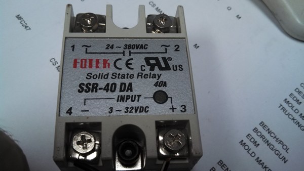
I just hooked up my pwm and wish I had done so sooner. Just need a heat sink for the ssr. It gets pretty warm.
 
If we're controlling 5500W elements, and I believe it's better to oversize things a little rather than sizing them at capacity, would this be a good fit for these elements? http://www.ebay.com/itm/6500W-thyristor-Voltage-Regulators-dimming-speed-thermostat-control-/160833921374?pt=LH_DefaultDomain_0&hash=item257272e15e

Not inexpensive, but would it eliminate the need for the SSR, and the thought of fewer parts, so the potential of less going wrong? Appears to be built appropriately beefy enough.

The circuit you listed seems to be as simple as it can get for a triac operation. It probably uses a diac, capacitor and resistor to provide the trigger to the triac. By the picture, the triac is the BTA60-800B which is a 40A triac. The frequency of switching will be 60Hz. My PWM works at very low duty cycle, something like 2Hz.
Also, triacs works better when switching at zero crossing of the sine wave (specially for inductive loads, not your case thought), which this one will not do. This may increase heat and reduce component life.
 
So this is my second time reading this thread I have all my parts ordered to make Walker's PWM just needed some quick info on one thing regarding the 30a switch. Am I looking for a 4 pin switch? Will this one work: http://www.ebay.ca/itm/1-x-Green-Button-4-Pin-DPST-ON-OFF-Illuminated-Car-Rocker-Switch-AC-250V-15-30A-/370725294852?pt=LH_DefaultDomain_0&hash=item5650f31304&_uhb=1

Also will the light on the switch come on only when the element is on?

That switch does look like it will work. This switch would handle the power coming from the wall into the box. So the light will come on when you turn it on but then it is the PWM that switches the element on and off. The PWM is after this switch so this switch would not be affected by the PWM.
 
Hello, I bought the FK804-2 PWM kit and a 2.2u cap, soldered it into C1 and powered it up with a 9v DC power supply. I get a constant 9v output, no oscillation. I can see oscillation on the 555 timer on the output (pin 3) but on the other side of the 300 ohm resistor, there is no oscillation. I'm stumped.
 
Bumble86 - That side of the 300 ohm resistor goes to the transistor, and the lead next to where it is soldered is connected to ground, you may have a solder jumper to it... that would be the most logical explanation.. If there is not, maybe the transistor is shorted, to test that theory, totally remove the transistor and remove all solder from those three holes with wick or suction tool... then measure the R300 output again.
 
Freddy's, so does the wall wart plug into a separate 120 v receptacle or does the hot leg spliced into it power it? Your diagram shows that one leg it spliced to power it. Little confused of how to wire at this point. The rest appears clear.
 
For people reading this thread for the first time, the LED dimmer can be made to do slow PWM by changing a single capacitor. See the link in my signature.
 
How would you guys like to be able to get rid of everything but the resistor and the SSR? How about a DIY kit with box, SSR, heat sink, cable glands, thermopaste, etc... http://www.stilldragon.com/diy-controller.html

While you are there, for $36, you can get a tri-clover element adapter..
http://www.stilldragon.com/element-guard-kit-and-adapters.html
(is 2" tri-clover and does require a 2" ferrule welded to your kettle and a clamp and gasket, but 2" is much easier to slip the element in)

I use the element adapters myself, and they are great, I built my own 555 PWM as shown earlier in this thread, but plan on using this kit to build for a friend..
 
So all i would need to get is the wiring components, receptacles & power switches?

When will you have instructions?
 
owentp said:
So all i would need to get is the wiring components, receptacles & power switches? When will you have instructions?

Does this also require a 120 to 12 v supply for the potentiometer to work?
 
Yes, it is complete, just 10/2 with ground wire and cord ends... no 12v supply or other electronics needed, it is all inside the special SSR... The seller is not me, just a company I have bought things from and happy with... (You cannot beat the element guards with a stick!). I think they are leery about giving instructions.. legal reasons of folks who shouldn't be playing with 240VAC thinking they can.... and I agree! It is simpler than PWM , you just hook 2 terminals of the resistor up (center and an outside, hook it up so zero ohms when turned fully clockwise), and the power side is hooked up just like and SSR is here...
 
You can find instructions for a similar controller on the Stilldragon forum. Apparently there were copyright issues with the original instructions.
 
This is a cool & easy kit. One question, their instructions show their SSR mounted to the heat sink & it is mounted inside the box entirely. Shouldn't the heat sink be on the outside of the box to dissipate the heat from the SSR?
 
Is there a way to wire this to 10/3 with ground for gfic? From what i understand? 3 wire will not trip the gfic.
 
Yes it will work and you don't need to change the resistor. But you need either install a fun or replace the heatsing to a much bigger one.
 
Is there a way to wire this to 10/3 with ground for gfic? From what i understand? 3 wire will not trip the gfic.

Obviously you should consult a certified electrician if you have any doubts, that is one of the foundations of the electric brewing forum.

That being said, A 240V GFCI has a the extra wire on the actual breaker in the panel, if it detects that current goes anywhere but in one of the legs and out the other, it trips. Logic would say that if they are good enough for a 240v hot tub, they are good enough for a brew kettle.

Again, you should consult an electrician if you are not completely sure of what you are doing.

-mike
 
thanks for the reply Brumateur, i wonder which is easier to do? (i'm quite practical)
Perhaps it has a step-down voltage inside, that i could connect a computer fan to?
hhmmmmm?
 
thanks for the reply Brumateur, i wonder which is easier to do? (i'm quite practical)
Perhaps it has a step-down voltage inside, that i could connect a computer fan to?
hhmmmmm?

Done right you don't need a fan. I have an SSR powered by a PWM that handles my 5500W heating element. I just purchased a heat sink rated for the circuit and attached with the supplied grease.
 
thanks for the reply Brumateur, i wonder which is easier to do? (i'm quite practical)
Perhaps it has a step-down voltage inside, that i could connect a computer fan to?
hhmmmmm?

I'd install computer fan powered from 9 or 12 Volt wall adapter.
 
Frustrating. Wired up my new SSR to my PWM controller and it doesn't cycle properly. If I have the pot turned all the way up it will light up the element. If I start to turn it down a little it stops turning on the SSR and doesn't turn it back on until I power the PWN off and back on again. The farther to the right I have it when I power it up, the longer it lights the SSR. When it's turned way down, it only blinks the SSR for a split second.

But each time it turns off, I have to power down the PWM and turn it back on again before it will power the SSR...

I've replaced the C1 with a 2.2 cap. It's got a B500K pot, which I think is linear.

The PWM circuit is a baktronics kit I put together a while back. Seemed to control a fan just fine before I swapped caps IIRC.
 
I will try and get a pic at lunch or after work. I did discover that the power supply I was using originally was a 9V adapter. I swapped in a 12V adapter last night, but no change.

I *could* swap the pot and 2.2 cap onto on of my homemade boards and try it. I was too busy last nigh to want to mess with it any further until had some advice from here on possible causes. I'm not sure what could be wrong with the board it's on, though. It's a prebuilt baktronics board, so I know the traces are correct.
 
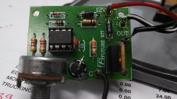
well, your 555 could be fried due to heat or static, the cap could be bad or incorrect, there could be hair of solder making contact between two things that shouldn't... a picture shows us what we are dealing with... they say it is worth a thousand words ;-)
 
Took some pics at lunch. I do have some spare 555s because I was going to build a few PWM controlled stirplates. It would be pretty easy to swap one out and try it.

IMG_20140513_112230_080.jpg


IMG_20140513_112156_168.jpg


IMG_20140513_112136_965.jpg
 
Back
Top