Building Stir Plate, BYO style

Homebrew Talk - Beer, Wine, Mead, & Cider Brewing Discussion Forum

Help Support Homebrew Talk - Beer, Wine, Mead, & Cider Brewing Discussion Forum:

This site may earn a commission from merchant affiliate links, including eBay, Amazon, and others.

DubbelDach

Well-Known Member
Joined
Apr 29, 2008
Messages
1,267
Reaction score
59
Location
Lancaster, PA
So using this: Build Your Own Stir Plate as a guide... I started acquiring parts.

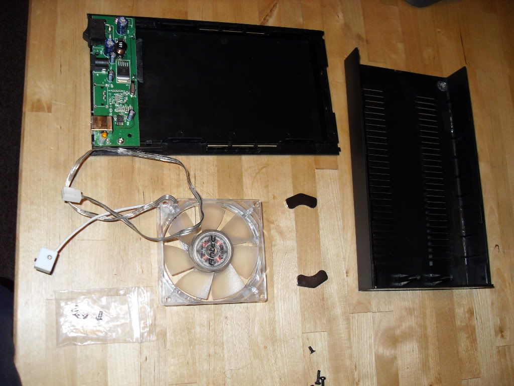
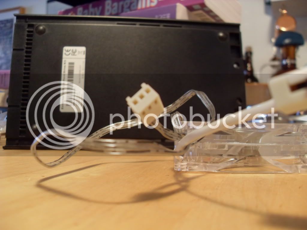
Got an 80mm multi-speed fan with sweet green LEDs, a black hard drive case with power switch incorporated, and two 25mm stir bars. Also salvaged two rare earth magnets from a hard drive set to be scrapped at work.

SDC14286.jpg


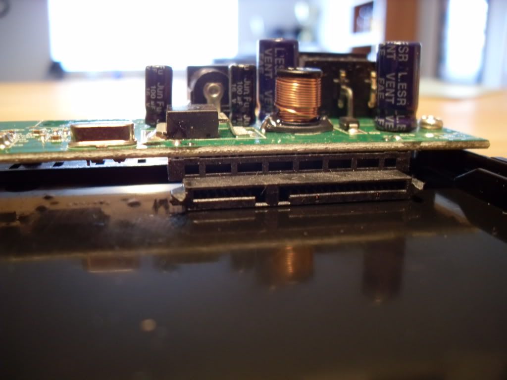
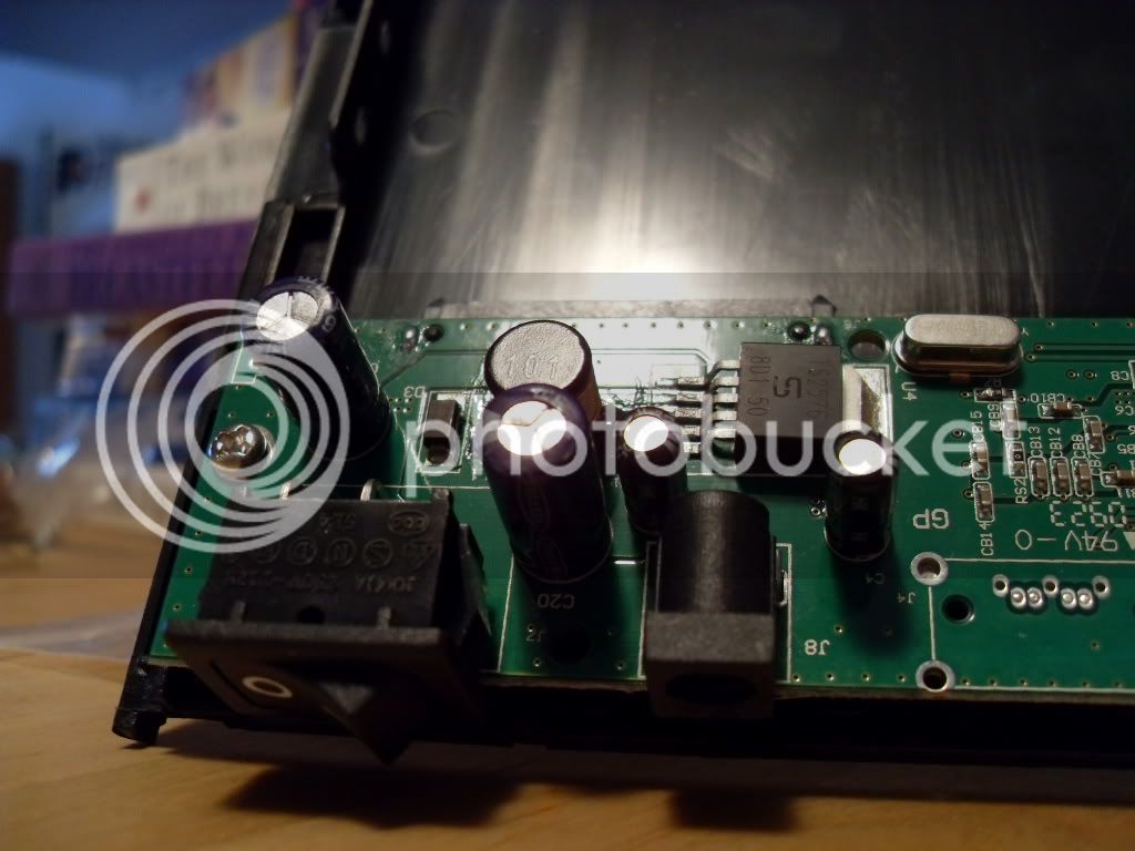
So.... I have limited electrical knowledge (read: none). Inside the case is a small board, and I'm wondering if it would be better to just splice the fan onto a cell charger and rig a different switch. There's no input on the board for the 3-hole plug on the fan (BYO article said to get a case with that, but me = fail). Anybody see anyway this can get hooked up?

SDC14280.jpg


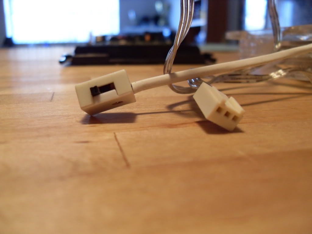
Here's the fan switch:

SDC14284.jpg


Rest of pics here, if they help... http://s281.photobucket.com/albums/kk238/shiplax27/Stir_Plate/ Thanks in advance!
 
You have all you need. The hard drive had to be powered by the device. So you just need to figure out what type of connection it had. I can't really tell from the picture but it looks like SATA. If so, get a sata power cable and cut one end off. You should have 12v and maybe 5v too on that plug.

I think that is a fantastic idea for a stirplate. You have everything you need all in a pre built case.
 
If I were you, and wanted to use the existing switch, I'd de-solder the switch from the electrical board, and solder on two lengths of wire to each of the posts coming off the switch. That way you're sure not to power the rest of the capacitors, resistors, etc that are currently existing on the board.

Then use those two new lengths of wire as pig tails and splice into the fan and cell phone charger, because there's really no way for you to plug and play with the items you have. You don't have to solder the fan and cell phone charger wires to the pig tails. Since this will be enclosed, there's nothing wrong with using small wire nuts to make your connections.

The only thing I'd caution you on, is making sure the switch is rated to handle the amps the fan will pull. Most likely you're not going to know what that switch is rated. It might be stamped on the plastic body of the switch? If that switch is rated for 1amp, and your fan pulls 2amps, you're going to burn out your switch, perhaps cause a fire. (I doubt that fan is that powerful, just using round numbers)

Same thing with the thickness of the wire you're using. If the fan has 22gauge wire, make sure not to use anything smaller than that anywhere in your circuit.

One last word of caution. Are you sure your fan is set up for DC power? Some of these small computer fans run on AC power. If that's the case, the cell phone charger isn't necessary, as it won't supply the motor with the correct power.

Is that other wire coming off the fan another switch, or is it a dimmer to control the speed of the fan?

Jay
 
Hopefully without being too disagreeable........

1. That last post is bad info. No computer fans run on 120v All computers are 12v 5v 3v. That is why they have power supplies. There is no line voltage in a computer case.

2. The existing circuit board will regulate the power a bit so you are better off using the existing circuit.

3. The switch will be rated plenty large enough for a fan. The motor on a hard drive will pull more amps then a fan........On the same note. why cut splice and solder when you don't need to.

4. If you read my first post you would have seen that He does in fact have all the parts for plug and play.... Well with one splice.

5. I work in IT. I disassemble and re-assemble computers all day and also build circuit boards for fun. Just in case there is a question about my knowledge of this subject.
 
Well, not all pc fans are DC, just google AC computer fan.

But I agree with you, this one is most likely DC, given the wire harness pic.

And I didn't see your post, as I was still typing mine when you posted.:)
 
I like the idea of the drive bay enclosure but I see a critical element missing, speed control. If I throw my fan on at max tilt it will toss the stir bar every time. I am only using one magnet so I don't know if the second magnet is enough to keep the stir bar coupled, I don't think it would.

Using the existing circuitry may be a problem. If you are going to use something like the lm317 to control speed you will have to put it in after the switching power supply circuit. (where the coil and caps are). That is if you intend to use the existing circuit.

Now, I would almost bet dollars to donuts that the silk screened box in the upper right hand corner by that power supply circuit is the output of that circuit for a fan. Take a meter and read the voltage on the two pad in that box to see if there is +12V DC. If there is here is what you do.

Cut the molex connector off the fan.
Splay the three wires out.
Strip the two outside wires back about a quarter inch.
Solder one wire to one pad and the second wire to the other.
The middle wire will not be connected (speed feedback wire)

This will still give you off/on control.
 
You have all you need. The hard drive had to be powered by the device. So you just need to figure out what type of connection it had. I can't really tell from the picture but it looks like SATA. If so, get a sata power cable and cut one end off. You should have 12v and maybe 5v too on that plug.

Pretty sure it's SATA:

SDC14289.jpg


Are there SATA to Molex connectors? I think I may take the whole thing to Radio Shack and ask...

Is that other wire coming off the fan another switch, or is it a dimmer to control the speed of the fan?
I like the idea of the drive bay enclosure but I see a critical element missing, speed control. If I throw my fan on at max tilt it will toss the stir bar every time. I am only using one magnet so I don't know if the second magnet is enough to keep the stir bar coupled, I don't think it would.

Three speed swith on the fan:

SDC14291.jpg


Hopefully without being too disagreeable........

1. That last post is bad info. No computer fans run on 120v All computers are 12v 5v 3v. That is why they have power supplies. There is no line voltage in a computer case.

2. The existing circuit board will regulate the power a bit so you are better off using the existing circuit.

3. The switch will be rated plenty large enough for a fan. The motor on a hard drive will pull more amps then a fan........On the same note. why cut splice and solder when you don't need to.

4. If you read my first post you would have seen that He does in fact have all the parts for plug and play.... Well with one splice.

5. I work in IT. I disassemble and re-assemble computers all day and also build circuit boards for fun. Just in case there is a question about my knowledge of this subject.

Good info!

DubbelDach I grew up in selinsgrove about 50 miles north of where your at, along the river.

You made the HBT shirt patches, right? I think we PMed about Selin's Grove... I was there for lunch yesterday. SNAFU IPA is awesome!


Thank you all! I look forward to seeing if there are SATA to Molex connectors... That seems to be the easy fix. Again, I'm not too sharp with electronics and soldering and such...
 
The only thing I'd caution you on, is making sure the switch is rated to handle the amps the fan will pull. Most likely you're not going to know what that switch is rated. It might be stamped on the plastic body of the switch? If that switch is rated for 1amp, and your fan pulls 2amps, you're going to burn out your switch, perhaps cause a fire. (I doubt that fan is that powerful, just using round numbers)

Markings on the switch: 10(4)A 250V~T125
 
So the Radio Shack guy had no idea what was up with this... Couldn't even tell if it was SATA or IDE connector and said they had nothing to bridge the gap between the fan and power.

The power cord that goes into the drive is an AC adapter... Input is 100-240v - 50/80mhz 0.8 A. The output is 12 v, 2 A.

EDIT: Can I plug my 3-pin fan into this: http://www.endpcnoise.com/cgi-bin/e/std/sku=3-PINto4-PIN

And then plug this: http://www.endpcnoise.com/cgi-bin/e/std/sku=single_SATA_power into my board?
 
You might just have to cut the end off the power for the fan.
Then cut the molex end off the sata cable you have in the second link.
Test the leads to see which ones give you +12v and splice them directly to the fan leads.

I am not sure the adapter you have on the first link will work. I would just splice given the choice. The three position fan speed switch may not give you that much range. The low setting might be all you can use. It is worth a shot. Other wise you might have to do what coderage said and get another type of speed control. I used a PWM circuit on mine.
 
Back
Top