BrothOfVigor
Well-Known Member
A huge bow is in order for all of the great folks on this board who have shared their ideas and continue to participate in discussion and development of really great homebrewing tools and solutions.
I have a tendency to go off the deep end on new hobbies, high as a kite on the thrill of something new and exciting, only to get burnt out and move on. To date, cooking and homebrew have managed to overcome this unfortunate, yet well intended, hurdle. From the days of watching Michiba create his famed "Broth of Vigor" on grainy mid 90's Iron Chef, I find the title to be equally fitting to a steaming pot of glorious wort. It was meant to be.
After reading threads on this board and finding Kal's www.theelectricbrewery.com it took a while to get over the "who needs a guest bedroom when I could be using it every day to make massive batches of beer"-phase (that happens to everyone right?). I decided to go small. In my case, go sane. To point out a few great resources that led me here, JKarps famed counter-top brutus, Resslerk's incredibly difficult to find using the search function cart of greatness, and more recently Jrb03's 110V e-biab thread full of fantastic information. After lots of lots of flip-flopping between the brutus, HERMS, and BIAB, I came to settle on the HERMS setup for a couple reasons:
-Potential step mashes
-No need to build a CFC, permanent "immersion" chiller
-Tame kettle size by having a separate mash tun.
-Counters that are not that well designed for a cooler sitting on top of a bucket.. (I know that ones lame but what can I say?)
I of course had to remain true to myself and avoid that voice in my head that said "make it affordable, you wont tell the difference when its all done!". So, the scratch to that itch: lots and lots of stainless compression fittings. My disclaimer to this build is that many parts could be done for less money, but I find compression fittings to be the best substitute for Legos. Plus you can get hell'a deals on Ebay! (So, still sort of cheap? Right voice? Right..) :rockin:
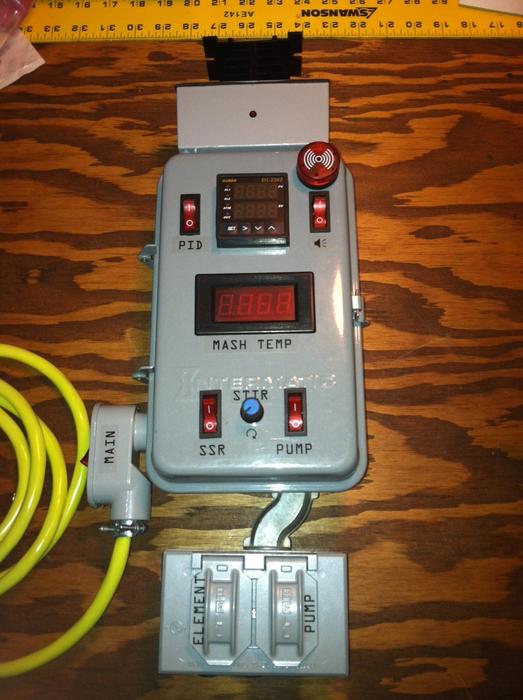
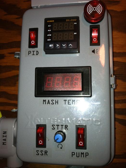
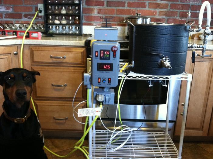
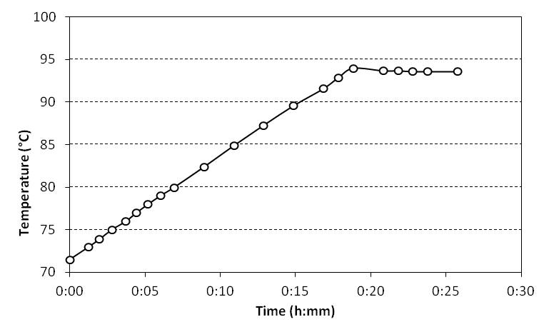
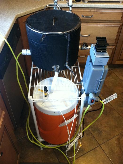
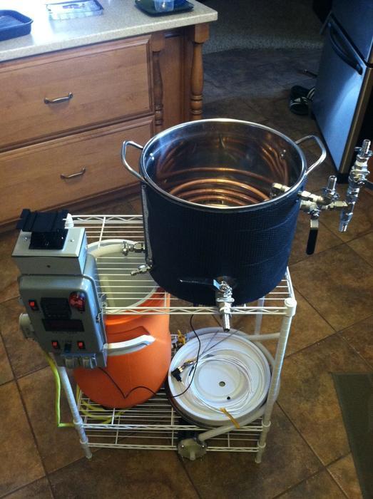
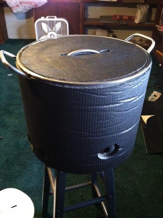
So to actually get somewhere with this post. Using a six gallon pot, five gallon round cooler (recycled from 2.5gal stove top all grain), single pump, and single 120V 2000W element, I hope to be making 3-4 gallon batches with great mash temperature control (Auber PID) using my kitchen GFCI outlets and vent hood.
Progress so far:
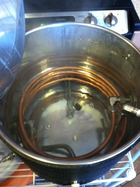
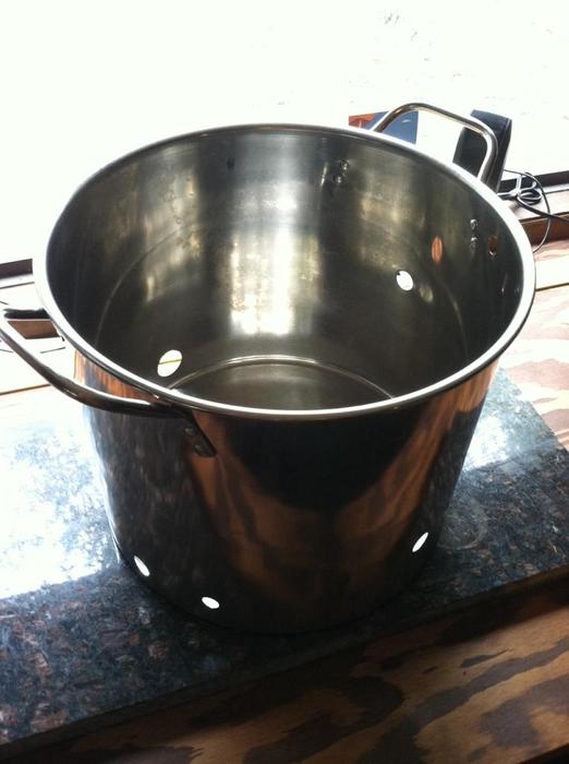
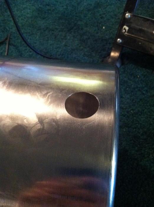
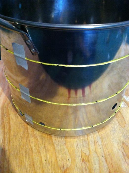
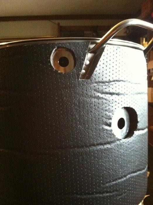
Using the cheapy Harbor Freight step bits I've popped all the holes in the kettle. It worked amazingly well, making perfect holes with no headaches. I just lubed it up with some cooking oil and away it went. Drilling the pilot holes with a wood bit was the hardest part, go figure. A total 6 holes went in.
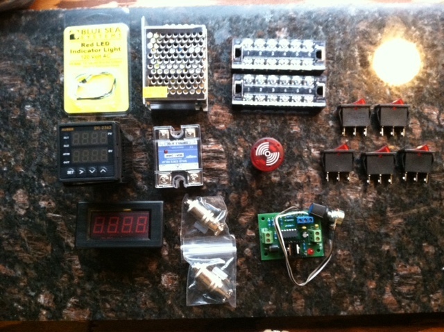
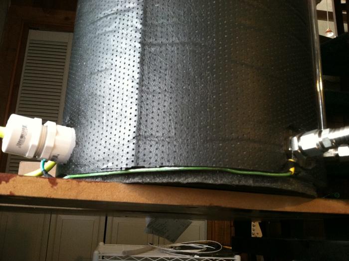
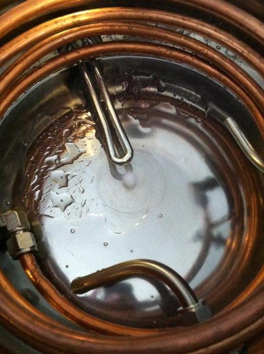
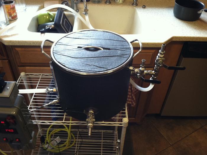
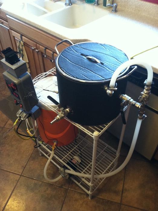
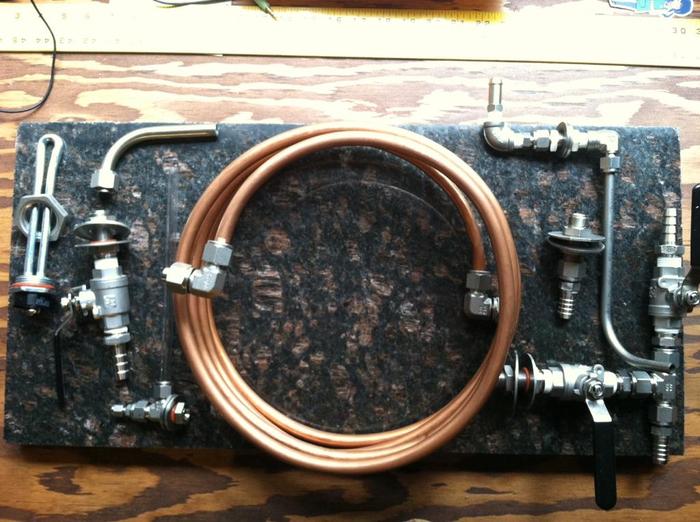
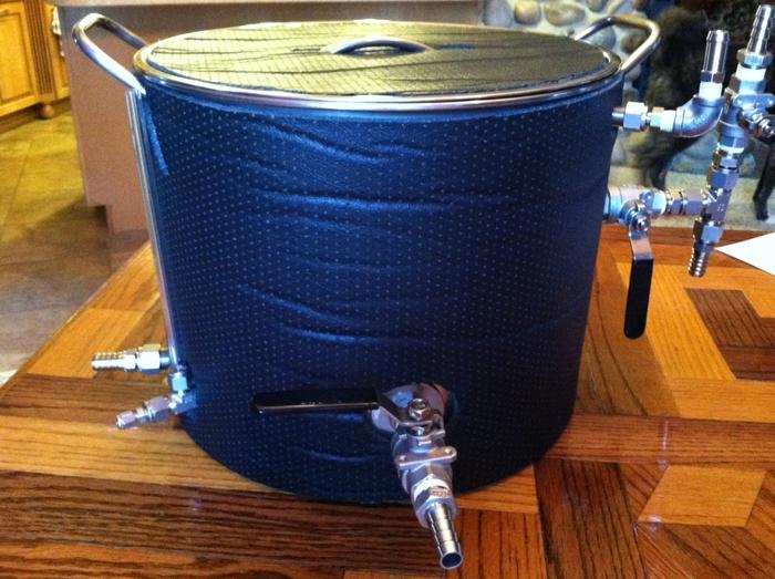
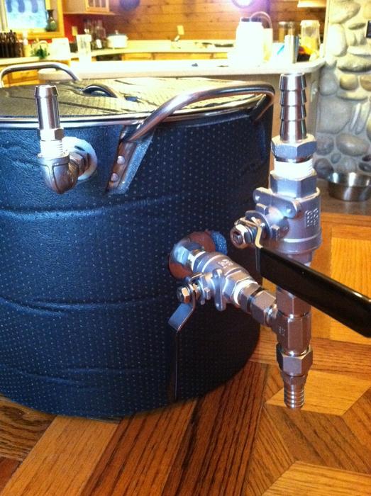
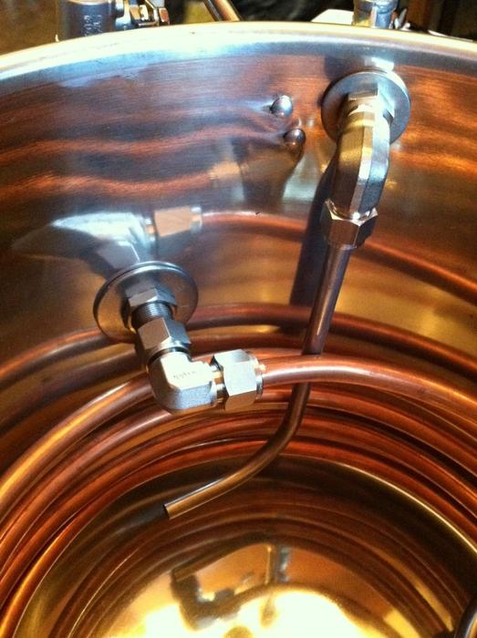
I've acquired all of my fittings needed (the word "needed" could be argued) after hounding Ebay for months. To list what is in the photo from left-ish to right-ish:
120V 2000W element - Ace Hardware
1" 304 locknut - McMaster
1/2" 304 stainless dip-tube for main outlet.
1/2" M-NPT to 1/2" compression bulkhead fitting - Ebay
1/2" 304 ball valve - Ebay
1/2" 304 M-NPT to 1/2" barb - BargainFittings
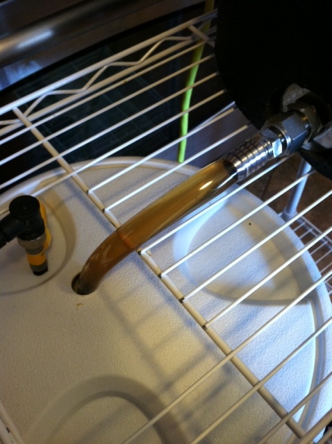
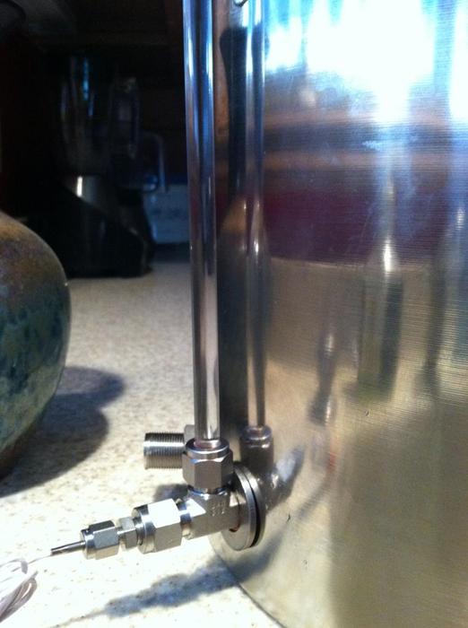
3/8" poly tube for sight gauge - McMaster
3/8" compression tee - Ebay
1/8" compression to 3/8" tube adapter, bored through - Ebay
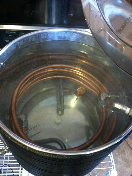
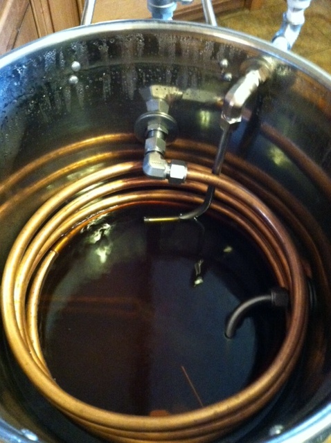
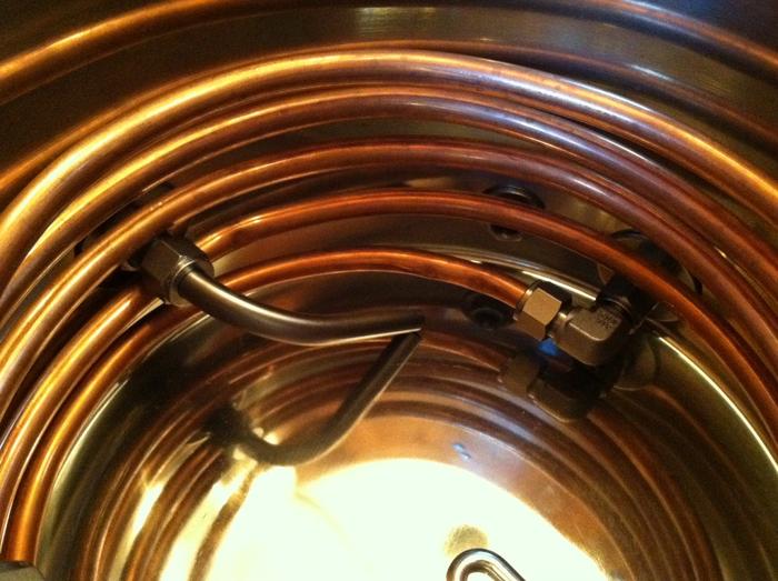
1/2" copper tubing for HERMS coil with 1/2" compression to tube adapters. -Ebay
1/2" hose barb to 1/4" M-NPT fitting - Ebay
1/4" M-NPT to 3/8" compression bulkhead fitting - Ebay
1/4" M-NPT to 3/8" compression elbow - Ebay
Above mentioned 1/2" bulkhead fitting with 1/2" hose to 1/2" tube adapter - Ebay
Valve assembly, including 1/2" pipe to tube bulkhead fitting, 1/2" M-NPT to compression adapters, 1/2" compression tee, and 1/2" hose adapters.
Nearly all fittings were about $8. Ebay is amaaazing.
The exact purpose of some of these items came in a "ooooh yeah that'd be great!" moment, so I got them only to realize "mmm, maybe not so great". But I have them now, so they must be used!
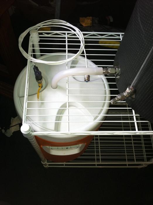
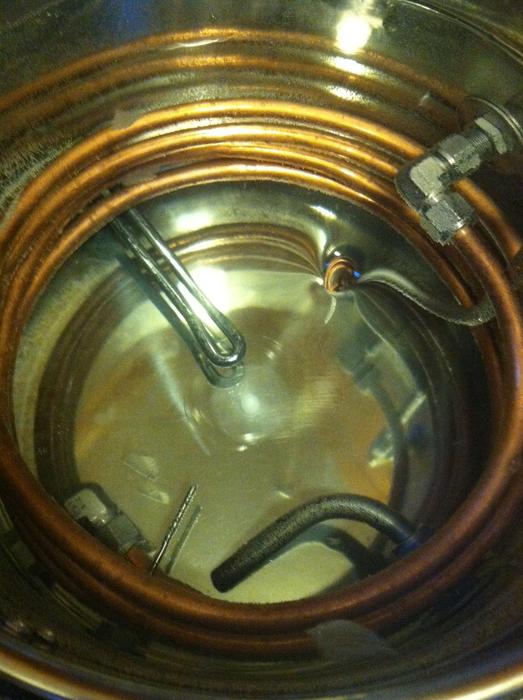
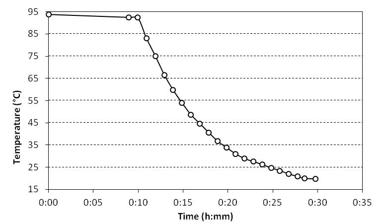
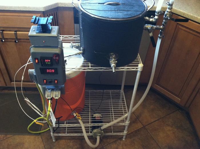
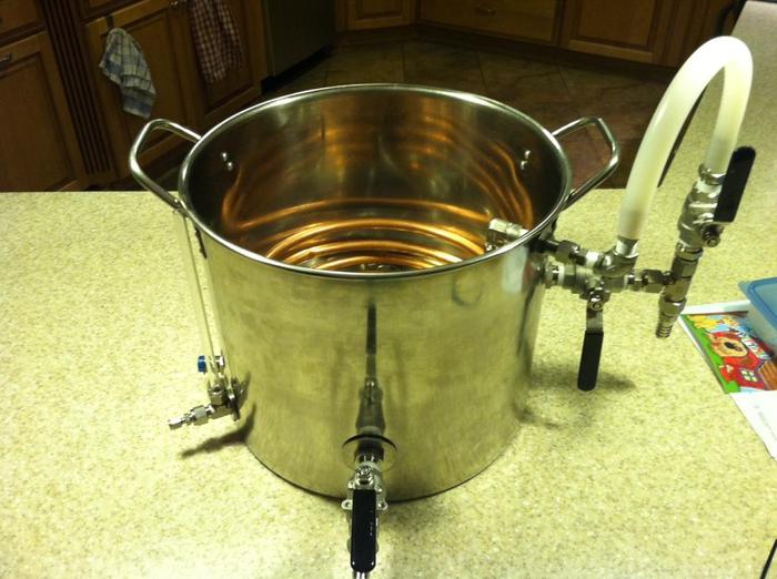
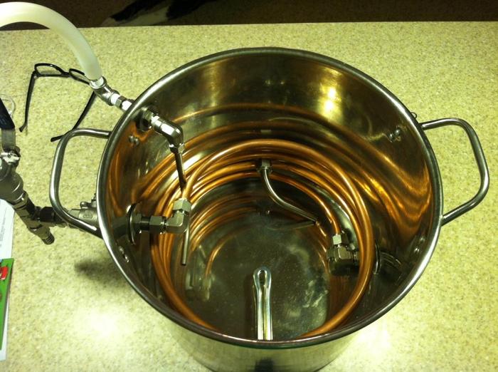
The general idea: Distilled and treated water is heated in the kettle and drained to the MT. The kettle is refilled to cover the coil, after which the element is set to the mash in temp and the pump begins to circulate (up through the valve assembly (bottom right of photo), going through the horizontal valve into the coil), bringing the cooler to equilibrium. The grain is then added, stirred, and constantly circulated at the set temp. After mashing the kettle is drained of water, (this is the really unnecessary part, get ready) the horizontal valve is closed slightly and the vertical valve is opened slightly, allowing wort to slowly fill the kettle (AWESOME NO HOSE CHANGE.... it seemed valuable late at night). After the kettle begins to fill, the coil can be shut off, allowing all liquid to enter the kettle. Boil as usual. After boil, the coil can be hooked up to tap water for cooling, and the pump can be attached to the kettle outlet and inlet for a whirlpool (I hope), increasing cooling efficiency and separating some coagulated gunk. Cooled wort is then drained right into the fermenter and off to the yeast races.
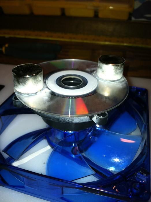
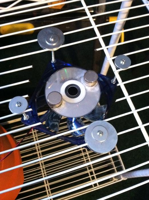
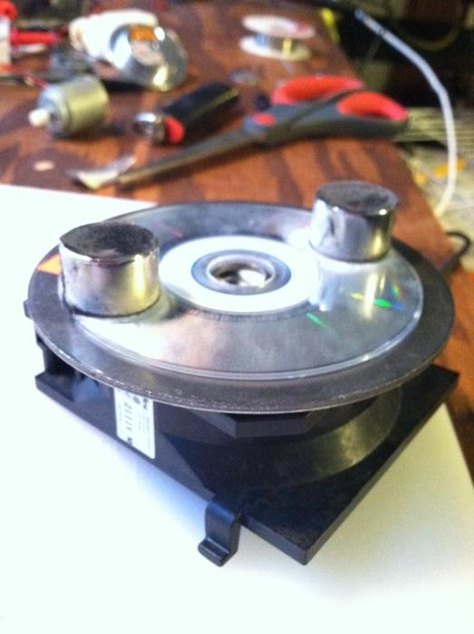
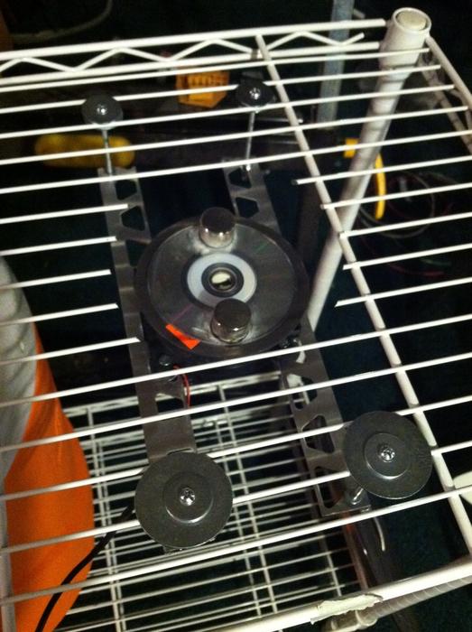
Maybe needlessly complicated. But it should look cool and save a little bit of stress I hope. Like I said, many features could be done with traditional bulkhead fittings or erased completely. I am thinking of adding a stir plate under the kettle to mix the water while mashing and cooling, thoughts? Has anyone achieved a worthwhile vortex from a stirbar in the kettle to separate solids after cooling?
If anyone actually read that whole mess, I am super stoked to start putting this together. I would love to hear any feedback and comments on this!
Thanks guys!
I have a tendency to go off the deep end on new hobbies, high as a kite on the thrill of something new and exciting, only to get burnt out and move on. To date, cooking and homebrew have managed to overcome this unfortunate, yet well intended, hurdle. From the days of watching Michiba create his famed "Broth of Vigor" on grainy mid 90's Iron Chef, I find the title to be equally fitting to a steaming pot of glorious wort. It was meant to be.
After reading threads on this board and finding Kal's www.theelectricbrewery.com it took a while to get over the "who needs a guest bedroom when I could be using it every day to make massive batches of beer"-phase (that happens to everyone right?). I decided to go small. In my case, go sane. To point out a few great resources that led me here, JKarps famed counter-top brutus, Resslerk's incredibly difficult to find using the search function cart of greatness, and more recently Jrb03's 110V e-biab thread full of fantastic information. After lots of lots of flip-flopping between the brutus, HERMS, and BIAB, I came to settle on the HERMS setup for a couple reasons:
-Potential step mashes
-No need to build a CFC, permanent "immersion" chiller
-Tame kettle size by having a separate mash tun.
-Counters that are not that well designed for a cooler sitting on top of a bucket.. (I know that ones lame but what can I say?)
I of course had to remain true to myself and avoid that voice in my head that said "make it affordable, you wont tell the difference when its all done!". So, the scratch to that itch: lots and lots of stainless compression fittings. My disclaimer to this build is that many parts could be done for less money, but I find compression fittings to be the best substitute for Legos. Plus you can get hell'a deals on Ebay! (So, still sort of cheap? Right voice? Right..) :rockin:
So to actually get somewhere with this post. Using a six gallon pot, five gallon round cooler (recycled from 2.5gal stove top all grain), single pump, and single 120V 2000W element, I hope to be making 3-4 gallon batches with great mash temperature control (Auber PID) using my kitchen GFCI outlets and vent hood.
Progress so far:
Using the cheapy Harbor Freight step bits I've popped all the holes in the kettle. It worked amazingly well, making perfect holes with no headaches. I just lubed it up with some cooking oil and away it went. Drilling the pilot holes with a wood bit was the hardest part, go figure. A total 6 holes went in.
I've acquired all of my fittings needed (the word "needed" could be argued) after hounding Ebay for months. To list what is in the photo from left-ish to right-ish:
120V 2000W element - Ace Hardware
1" 304 locknut - McMaster
1/2" 304 stainless dip-tube for main outlet.
1/2" M-NPT to 1/2" compression bulkhead fitting - Ebay
1/2" 304 ball valve - Ebay
1/2" 304 M-NPT to 1/2" barb - BargainFittings
3/8" poly tube for sight gauge - McMaster
3/8" compression tee - Ebay
1/8" compression to 3/8" tube adapter, bored through - Ebay
1/2" copper tubing for HERMS coil with 1/2" compression to tube adapters. -Ebay
1/2" hose barb to 1/4" M-NPT fitting - Ebay
1/4" M-NPT to 3/8" compression bulkhead fitting - Ebay
1/4" M-NPT to 3/8" compression elbow - Ebay
Above mentioned 1/2" bulkhead fitting with 1/2" hose to 1/2" tube adapter - Ebay
Valve assembly, including 1/2" pipe to tube bulkhead fitting, 1/2" M-NPT to compression adapters, 1/2" compression tee, and 1/2" hose adapters.
Nearly all fittings were about $8. Ebay is amaaazing.
The exact purpose of some of these items came in a "ooooh yeah that'd be great!" moment, so I got them only to realize "mmm, maybe not so great". But I have them now, so they must be used!
The general idea: Distilled and treated water is heated in the kettle and drained to the MT. The kettle is refilled to cover the coil, after which the element is set to the mash in temp and the pump begins to circulate (up through the valve assembly (bottom right of photo), going through the horizontal valve into the coil), bringing the cooler to equilibrium. The grain is then added, stirred, and constantly circulated at the set temp. After mashing the kettle is drained of water, (this is the really unnecessary part, get ready) the horizontal valve is closed slightly and the vertical valve is opened slightly, allowing wort to slowly fill the kettle (AWESOME NO HOSE CHANGE....
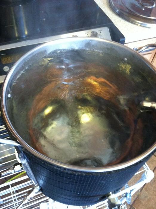
it seemed valuable late at night). After the kettle begins to fill, the coil can be shut off, allowing all liquid to enter the kettle. Boil as usual. After boil, the coil can be hooked up to tap water for cooling, and the pump can be attached to the kettle outlet and inlet for a whirlpool (I hope), increasing cooling efficiency and separating some coagulated gunk. Cooled wort is then drained right into the fermenter and off to the yeast races.Maybe needlessly complicated. But it should look cool and save a little bit of stress I hope. Like I said, many features could be done with traditional bulkhead fittings or erased completely. I am thinking of adding a stir plate under the kettle to mix the water while mashing and cooling, thoughts? Has anyone achieved a worthwhile vortex from a stirbar in the kettle to separate solids after cooling?
If anyone actually read that whole mess, I am super stoked to start putting this together. I would love to hear any feedback and comments on this!
Thanks guys!
 Slow and steady.