RIMS for Dummies

Homebrew Talk - Beer, Wine, Mead, & Cider Brewing Discussion Forum

Help Support Homebrew Talk - Beer, Wine, Mead, & Cider Brewing Discussion Forum:

This site may earn a commission from merchant affiliate links, including eBay, Amazon, and others.
How about doing it this way. It will require a DPDT Center Off switch. It should give you the control you want. If the element is energized the pump is also. The switch in the other position energizes the pump and disconnects power to the element. (BTW -With a 120V system you do not need to switch the neutral.)

Hope this helps.

I thought about doing that way - actually, just using one pole of the DP/ST switch to switch the pump, the other to switch the heater feed. The reason I didn't is because these are illuminated switches. I assumed there had to be a neutral at the switch for them to illuminate. I'm not sure thought as there is no iring explanation for the illumination...
 
I thought about doing that way - actually, just using one pole of the DP/ST switch to switch the pump, the other to switch the heater feed. The reason I didn't is because these are illuminated switches. I assumed there had to be a neutral at the switch for them to illuminate. I'm not sure thought as there is no iring explanation for the illumination...
If you can do it with a DP/ST switch I'd like to see that. I cannot even begin to imagine how you would be able to control the element and the pump, the way you want, using it.

For the switch illumination you do need the neutral at the switch, however, you do not need to switch it. It is there only to complete the circuit for the lamp.
 
Well this seems to be the right place to ask. I'm putting my first build together and want to go RIMS.

I seem that most are using 120 ULW elements. I have 220/50A available and plane to do an electric BK as well. Does anyone have experience running this style of RIMS with a 220 say 5500w or 6000w element? I have read all 57 pages now and seems that most people feel the PID can switch the element on and off fast enough to keep the set point without scorching.

I am debating building one with this style or just buying one of brewersequipment.com ones (made longer for the larger element) but I don't like how the temp sensor seems to be out of the flow path with the brewersequipment one.

What do you think?
 
What do you think?

I think the PID will do a fine job of switching the element on and off to maintain your temps w/o scorchng. The key is to tune the system so it doesn't overshoot the temperature. Most PIDs have an auto learn feature that will tune the PID based on the system it is controlling.
 
I cannot even begin to imagine how you would be able to control the element and the pump, the way you want, using it.

QUOTE]

I'm not following what you mean. There's no real difference between what you re-drew and my original in term of energizing the protection relay. Good point about not switching the neutral - but is there a down side to doing so?

When the pump switch is closed - the pump will run and the protection relay will be energized, completing the circuit from the PID output relay, allowing the PID to switch the heating element based on the PID settings. If the pump is not turned on, the element cannot heat - which I see as a safety feature for not being able to heat wort that is not moving.

My original question was - should I have the protection relay coil in parallel to the pump as per my original drawing the the following one (with the DP/DT)?

The reason for this question is - if the protection relay coil was in series with the pump, and were the pump circuit to fail, the the heater would not be able to be energized. This seems that it would provide greater protection, but I don't know if I can put the resistive load (4K4 ohms) of the coil in series with he pump and have both the pump and coil function correctly.

Ian
 
I think the PID will do a fine job of switching the element on and off to maintain your temps w/o scorching. The key is to tune the system so it doesn't overshoot the temperature. Most PIDs have an auto learn feature that will tune the PID based on the system it is controlling.

My PID does a good job, it does not overshoot and heats a 10 gallon mash about 3 degrees per minute in a 10 gallon round cooler. I ran it on the auto tune function with just water in the mash tun. It heats to the point where the water passes the set temperature, then let's it cool - it does this three times and depending on the response time, the AI will calculate when to turn off the heater so that it will not then rise above the set temperature. It is very easy to use.

I currently have a long 240V heater running at 115V. I have just bought a Stout Tanks 20g mash tun with RIMS tri clamp fittings and the tri-clamp RIMS tube from Brewershardware.com.

Consequently, I am re-doing my control box in a newer box and adding a DIN timer to time the steps. I want to add a protection relay and interlock the heating element to the pump to prevent heating when the wort is not pumping - hence the diagram and question a few posts ago.

My current RIMS tube is soldered copper and not really easy to clean - I'm looking forward to using the SS tri-clamp one.
 
I am debating building one with this style or just buying one of brewersequipment.com ones (made longer for the larger element) but I don't like how the temp sensor seems to be out of the flow path with the brewersequipment one.

What do you think?

I went with the brewersequipment on and it works quite well...have two brews under my belt with it already.

The newer versions that he is putting out has the outlet more towards the temp sensor...so a 4 inch sensor will be in the flow, no problem.
 
...
The reason for this question is - if the protection relay coil was in series with the pump, and were the pump circuit to fail, the the heater would not be able to be energized. This seems that it would provide greater protection, but I don't know if I can put the resistive load (4K4 ohms) of the coil in series with he pump and have both the pump and coil function correctly.
Short answer - You cannot put the coil in series with the pump. With that wiring setup, neither will work and both will fail.
 
Great read, only took me like 3 hours lol.

I'm about to go from 3 gallon BIAB batches to 10 Gallon batches and I'm definitely going to use a RIMS setup similar to this. I have plenty of questions spread across the site, but this one I think belongs here.

Is anyone using 2 heat exchangers (RIMS Tubes, whatever)? My idea is basically heat HLT with #1, Mash with #2 while heating sparge with #1, Fly sparge, Boil with 1. And as I get used to the process I can begin heating the HLT for a second batch.

They will both be 240V elements with PIDs, I'll use manual mode for the boil.

Any problems with this?

I don't know of anyone that's boiling with a RIMs tube and I think it would cause you some problems...

1. - Typical magnetic pumps we use don't work so well with boiling liquid, they tend to cavitate.

2. - You can certainly generate enough power to boil the small amount of liquid in the RIM's tube, but I think you'd have a hard time controlling it. In a closed vessel, the RIMS tube, you'd generate steam which means pressure.

Why not just mount an element in your HLT/BK and use RIM's for maintaining the mash temps as it was designed?
 
If you mounted a RIMS tube vertical on the side of the vessel with the input toward the bottom of the vessel and the output at the top, you could probably boil without a pump using convection to circulate.
 
If you mounted a RIMS tube vertical on the side of the vessel with the input toward the bottom of the vessel and the output at the top, you could probably boil without a pump using convection to circulate.

Sounds like you have conviction in that convection! :cross:


RIMS is not really meant to boil with...at least that is what I always thought. Besides, why would you?!? :tank:
 
If you mounted a RIMS tube vertical on the side of the vessel with the input toward the bottom of the vessel and the output at the top, you could probably boil without a pump using convection to circulate.

Seems like there would be a chance of scorching the wort?

What is the benefit of of using a RIM's tube in that way that would even justify the cost of the material?

I'm not understanding what the intended goal is.
 
Maybe to keep the element out of the vessel to get a better whirlpool. If the tube was isolated with valves, you could replace the element even if your vessel was full. And it would look cool?

I dunno, it was just a thought, though I have seriously considered mounting a RIMS tube to the outside of the mash tun to make a standalone mashtun with strike/sparge water on demand.
 
klyph said:
I dunno, it was just a thought, though I have seriously considered mounting a RIMS tube to the outside of the mash tun to make a standalone mashtun with strike/sparge water on demand.

You need a lot of power to get on-demand strike/sparge water from a RIMS tube. Raising water from 55 degrees to 155 or 170 degrees is a real challenge. There are several posts on HBT with the math to support this challenge.
 
I've done it, a 5500w 240v element can give you a 100 degree temperature differential at a pretty decent flow rate. If you are using room temp water or even hot water from the heater, it's definitely possible.

Here's a terrible video I made using a 5500w element to achieve a 110 deg differential with a decent enough flow rate for sparging.
I need to redo it with a gate valve and with the RIMS in/out ports facing up. I also need to definitively measure the output, but from the looks of it, you could sparge or strike with it.
 
Last edited by a moderator:
I've done it, a 5500w 240v element can give you a 100 degree temperature differential at a pretty decent flow rate. If you are using room temp water or even hot water from the heater, it's definitely possible.

Here's a terrible video I made using a 5500w element to achieve a 110 deg differential with a decent enough flow rate for sparging.
I need to redo it with a gate valve and with the RIMS in/out ports facing up. I also need to definitively measure the output, but from the looks of it, you could sparge or strike with it.
http://www.youtube.com/watch?v=u9X8s07MJ-A

It is definetely not "on demand". It took almost 5 minutes to get to temperature. You may get enough for fly sparging but you will still need an HLT because it looks like it could take a very long time to get any volume of strike water. If you need an HLT for strike water you may as well use it for sparging so what would be the benefit?
 
It is definetely not "on demand". It took almost 5 minutes to get to temperature. You may get enough for fly sparging but you will still need an HLT because it looks like it could take a very long time to get any volume of strike water. If you need an HLT for strike water you may as well use it for sparging so what would be the benefit?

It only took the time for me to get the valve set at the correct flow, otherwise it was instantaneous as it was flowing in a single pass. I'll measure the flow rate next time, as until then, this is all conjecture. However, if you consider the time it takes to fill the HLT and then heat to strike temps, I doubt it will be significantly less time than slowly filling the mash tun with water that's already up to temperature.

And even if it only works for sparging, there's no reason you can't use your kettle to heat the strike water and eliminate the HLT altogether.

I agree you can heat your strike water in your Boil Kettle eliminating a vessel. I still don't like it for strike water because there will cooling of the water as you fill if the best flow is just good enough for sparging.
 
Thanks for the input guys. My thinking was 2 fold...flexibility and safety. I want to be able to control the HLT and MLT temps, I want to brew all electric (although I'm still trying to figure out if my current situation will facilitate that). I entertained the idea of a RIMS tube and a heatstick, but seeing the heatstick builds scared be a bit, I don't like the idea of the connections being underwater in a failure situation. I also would like to minimize the about of holes I drill in my aluminum kettles should my circumstances change (electric vs. gas). BUT I'm open to suggestions, and if a RIMS tube for boiling is going to be problematic then I won't do it.

Honestly at this point I may give up on ALL electric for now and go with a 120V rims tube and gas fired HLT. idk
 
It was tough for me to make the commitment to drill 1" holes in my vessels, but I've never looked back.

Electric>Gas in almost every way I can think of.
 
Aw, but you don't get to play with fire. I love that stuff.

About hot water heater elements being screwed into tapered female fittings, it wasn't a problem for me because the threads on the element are not long at all. Also, instead of spending lots on a tap, why not just use a dremel to remove a few threads from the ID of the coupler? This should do the trick just fine. Remember, you only need enough threads to tighten it down (not strip) because the threads aren't sealing anything, the gasket does.
 
After reading this entire thread I was wondering if someone could put together a parts list so that a person who understands RIMS but not controllers and the electrical side can purchase the items and have a buddy who does know about the electrical side assemble it =). At the beginning of the thread there is a awesome parts lists but I don't think it includes the controller, etc.. Also, since the beginning of the thread, people have come up with modifications and better ideas so I don't know if it makes sense to update the parts list and add electrical components?

I think it would actually be a good thing for this thread to kind of sum it all up.

Along the lines of what I said above, and if my request cannot be met can someone point me in the right direction, I would appreciate it. My system right now is not automated at all, what I want to do is add a tri-clamp RIMS tube with a basic controller that will recirc. the mash. I was also hoping that I can recirc. the HLT in the same RIMS tube. Can that be done?

-Dave
 
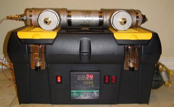
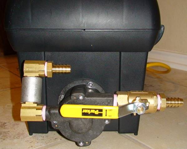
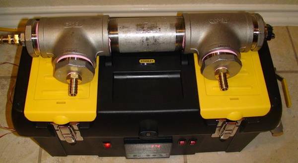
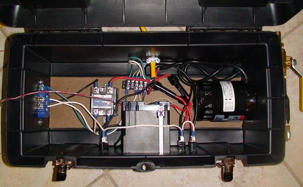
Got most of my build done today after the replacement RTD probe & 1/2 to 1/4 adapter arrived. Here are some pics. I'll likely start my own thread to detil the build once I get it completely done. Idea is a tabletop-type design that can store in minimal space. The RIMS will not rest on top of the control/toolbox during use. It will hang vertically on the side of my 10 gallon rubermaid, with the element-end on the bottom. Thanks Sawdustguy for the inspiration.

The toolbox:
jrfuda_RIMS_1_.JPG


Pump mounted on toolbox:
jrfuda_RIMS_3_.JPG


Detail of RIMS manifold:
jrfuda_RIMS_2_.JPG


Detail on wiring:
jrfuda_RIMS.jpg

Ok so I am trying to put together a rims. I have some of the parts but I am trying to figure out what else I need and how to hook them up. looking at your picture with the tool box open I have the SSR and the PID, but what is that part just north of the pid? Is that what is called a bus and if so what is it's purpose? What is the part on the left side of the tool box oppisite of the pump?

Thanks
 
Dave-

I have not put together a parts list yet, but am currently working on documenting my particular RIMS setup on my website, mersonbrewing.com. Shortly I will have the wiring schematic up for my control box.

As far as the hlt, yes, with an additional valve manifold. Right now I am able to mash or heat the hlt, but what I actually do is heat the hlt water separately, then use the rims to maintain the hlt temp while I sparge.
 
but what is that part just north of the pid? Is that what is called a bus and if so what is it's purpose? What is the part on the left side of the tool box oppisite of the pump?

Thanks

The bus is kind of like a power distribution center for the toolbox. You hook up your load wire to the tab and jumper the connections on one side. You can then add several load lines to each device needing power without having to twist them all together.
 
The thing opposite is the SSR if that is what you are refering to...otherwise it appears to be a connectior for the temp probe
 
The bus is kind of like a power distribution center for the toolbox. You hook up your load wire to the tab and jumper the connections on one side. You can then add several load lines to each device needing power without having to twist them all together.

Thanks obviously I need to do more research before I start messing with this.
 
I'll bite!

Are you looking for a controller or a controller and a RIMS tube? I've done both and they both work very well.

Let me know.

Samples of my work:

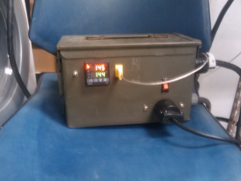
IMG00008-20101216-0929.jpg


PICT3947.jpg


PICT3946.jpg


IMG00017-20101216-0940.jpg


Paul Murphy
 
Paul,

I brew beer, but I am not an engineer, nor an electrician. I need a panel to run electrical on a heater and keep the heat er at the right temp. I run propane burners to bring the water up to strike temp. Perhaps a simple Johnson controller that I have will keep the right temps I need.


My specialty is stirring the mash and boiling the wort. I just moved up to a double pump single tier after twenty + years of brewing and would like to have a tighter control on mash temps. I have no desire to automate just have stricter control on my temps.

Well, there is no automation to my box other than keeping the temps maintained. After you mash in set the desired temp to be maintained. Then once your mash is set (about 10 min), you start the pump by flipping a switch. When the RIMS tube is full and wort is recirculating back into the tun, turn on the element with the flip of another switch. Temps will be maintained by the PID via the RIMS tube. When you're done with the mash turn off the element and pump. Move your pump output to your boil kettle and turn the pump back on to empty the tun. Add your sparge water to the tun, stir, etc then pump that into the kettle. It's pretty easy.

Clean up is easy as add'l unused sparge water can be pumped through the RIMS tube.

PM me if you are still interested.

The ordinance box is cool too. Makes the setup somewhat portable.
 

Latest posts

Back
Top