Countertop Brutus 20

Homebrew Talk - Beer, Wine, Mead, & Cider Brewing Discussion Forum

Help Support Homebrew Talk - Beer, Wine, Mead, & Cider Brewing Discussion Forum:

This site may earn a commission from merchant affiliate links, including eBay, Amazon, and others.
JK is right on. After some experimenting and a lot of "Pol" reading on here, a 7 gal boil with one 2KW element will not cut it. I built my clone with two 2KW elements and it will give 7 gallons a rip roaring boil. I plug my second element into a separate circuit in my kitchen for the boil and throttle the other element in my PID back to 75%. This gives me 3500W for my full boil.

Sorry to go off topic here but I keep seeing 75%=3500W output and I dont get it.

I have an auber PID and when put into manual with a value of 75% it still is max wattage but the duty cycle is changed to 75%. I can hear my kettle with a 4500W element die down and then go to a roaring boil and continue to cycle. My At is set to 0 so it isn't because my minimum duration is set too high. It sure as heck isn't PWM because it is entirely way too slow.

Unless you mean 75% is the average of x many Watts over 100% cycle time, you are still blasting your wort with 100% power.

I believe there is an allusion that you can fine tune the amount of instantaneous heat being applied to the wort, which isn't true. At least not with this equipment.

I'm certainly no expert when it comes to PIDs, hell, JK drew me a diagram on how to wire it. I just know when I set my PID to 75% with my other element on 100%, I get a roaring boil on 7 gallons. That's all I need to know.
 
I'm certainly no expert when it comes to PIDs, hell, JK drew me a diagram on how to wire it. I just know when I set my PID to 75% with my other element on 100%, I get a roaring boil on 7 gallons. That's all I need to know.

I wasn't directing anything at you bud. I have seen that math pop up here and there and it always kind of struck me funny. With several brews on my new system I finally felt experienced enough to say something.
Perhaps I have something set up wrong.

You are right. End of the day it does help control boil off rates which is all that matters.

Oh no problem, I am always happy to admit where my knowledge ends. Now I will wait for Pol to chime in and expand my knowledge. :mug:
 
You're absolutely right CodeRage. Elements are either on or off. 75% is the percentage of the time they're on.
 
JK, I just saw a pic of Sacc's sparge "arm" on his no sparge thread. Do you think there is a benefit to dispersing the recirculation water in the MLT like he does? As an old fly sparger, I have a small concern about dumping the recirculation water in the same spot over and over again. Just curious if you think this has any effect on the final product.
 
Sorry to go off topic here but I keep seeing 75%=3500W output and I dont get it.

I have an auber PID and when put into manual with a value of 75% it still is max wattage but the duty cycle is changed to 75%. I can hear my kettle with a 4500W element die down and then go to a roaring boil and continue to cycle. My At is set to 0 so it isn't because my minimum duration is set too high. It sure as heck isn't PWM because it is entirely way too slow.

Unless you mean 75% is the average of x many Watts over 100% cycle time, you are still blasting your wort with 100% power.

I believe there is an allusion that you can fine tune the amount of instantaneous heat being applied to the wort, which isn't true. At least not with this equipment.

Think of your element like a fuel injector in your vehicle unless your vehicles have carbs, 19 carb only 2 FI vehicles and bikes in my collection call it original show and old school. The injectors operatE by the same duty cycleS, % time open flowing gas vs time closed no with no gas flow. Same asCodeRage stated above just another example. The only way to get a reduced voltage would be like a dimmer that chops the the tops of the wave cycle down hence a lower voltage causing the lamp to dim down. In this case a 5KW or 10KW dimmer would be way out of the question in just cost alone for brewing. I'll keep a VFD out of this topic as this is for motors not a resistance load.
 
Congratulations on your BYO article nice job! It is nice to see how many on this forum have got into a magazine or publication. It would be interesting to find out how many. :mug:
 
JK, I just saw a pic of Sacc's sparge "arm" on his no sparge thread. Do you think there is a benefit to dispersing the recirculation water in the MLT like he does? As an old fly sparger, I have a small concern about dumping the recirculation water in the same spot over and over again. Just curious if you think this has any effect on the final product.

When I was originally designing this system I had planned on doing a sparge arm of some sort. I think it was Jamil and Palmer who talked me out of it in a brew strong episode when they said as long as there's a layer of water / wort on top of the grain bed (as there should be), the sparge arm is pointless. I just run a hose down from the MLT lid that rests on top of the grain bed to avoid splashing. There's always a nice thick protein sludge layer on top of the grainbed after everything runs out to the kettle so it seems to be working well.
 
When I was originally designing this system I had planned on doing a sparge arm of some sort. I think it was Jamil and Palmer who talked me out of it in a brew strong episode when they said as long as there's a layer of water / wort on top of the grain bed (as there should be), the sparge arm is pointless. I just run a hose down from the MLT lid that rests on top of the grain bed to avoid splashing. There's always a nice thick protein sludge layer on top of the grainbed after everything runs out to the kettle so it seems to be working well.

Thanks, I figured you had thought of it. Nothing like busting out two homebrew heavyweights to back it up! I'll go back to my little noob corner over here. :p
 
Great looking setup and most likely the model I will use to transition to AG. Now I will admit I am not the sharpest knife in the drawer, but I have been looking at your pics for the last two nights and still have a nagging question. How is the chilled water for the CFC separated from the recirculating wort? From the top pic of the pump/CFC it appear that they are plumbed together. What concept am I missing in the design? Any clarity for my lack of understanding will be greatly appreciated.
 
Great looking setup and most likely the model I will use to transition to AG. Now I will admit I am not the sharpest knife in the drawer, but I have been looking at your pics for the last two nights and still have a nagging question. How is the chilled water for the CFC separated from the recirculating wort? From the top pic of the pump/CFC it appear that they are plumbed together. What concept am I missing in the design? Any clarity for my lack of understanding will be greatly appreciated.

A counterflow chiller flows the chill water from your tap through the garden hose. The hot wort flows through the copper tubing inside the garden hose. They flow in opposite directions and never come in contact with each other. The hot wort flows into the bottom of the bucket and out the top in this setup. The chill water flows in at the top of the bucket and out of the bottom back into your sink in this setup. They are not plumbed together. This is a how a CFC (counterflow chiller) is built.
 
Thanks for the additional info. When I look at the pic of the CFC on the 1st page of this post it looks like the the upper chill hose tees into the upper wort transfer line. For some reason this is just not making since to me. The wort supply is plumbed through the ball valve that is connected to a short piece of silicon tubing which is then connected to a tee which seems to have the exterior chill hose and the interior spiral tubing wrapped in what appears to be garden hose all meeting at this union. That for some reason this has me perplexed and trust me I can walk and chew gum at the same time but this is just not making since. Sorry to be a pest but clarification would be appreciated. The light bulb just hasn't lit for me yet. I tried to bring that picture into my post but was unable.
 
The light bulb finally came on. The wort line runs inside the CFC line. Man I don't know why I didn't see that. Im gonna start collecting parts today. Thanks for the info.
 
Jkarp,

Can you detail the SS braid/coupling on your MLT? I want to try this system instead of a false bottom/copper manifold. Thanks, your system looks great, but since I just bought a turkey fryer... I guess I'll go the traditional route.

Thanks!
 
Can you detail the SS braid/coupling on your MLT? I want to try this system instead of a false bottom/copper manifold. Thanks, your system looks great, but since I just bought a turkey fryer... I guess I'll go the traditional route.

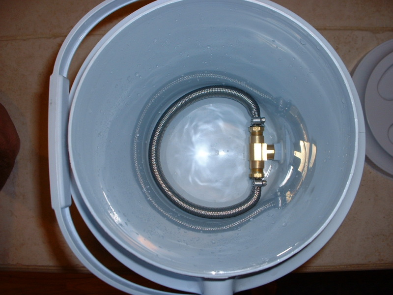
Here's a close-up of the inside. It's simply the stainless braid off a heavy-duty washing machine hose, 2 male 3/8" barbs and a 3/8" female tee.

beer25.jpg
 
Great job JKarp.
I too do small batches, BIAB to be exact. I love your design and will be building one myself. Once question, how long is the total chiller length? Also what is your kettle's boil off rate?
Thanks again!
 
Great job JKarp.
I too do small batches, BIAB to be exact. I love your design and will be building one myself. Once question, how long is the total chiller length? Also what is your kettle's boil off rate?
Thanks again!

My chiller is 20 feet. I couldn't squeeze any more in without crowding the pump connections. At least one person building this system is using the March pump with the center input. This simplifies the input connection greatly (wish I'd have thought of it), and it could make squeezing in a couple extra feet of chiller possible.

My boiloff rate is .75 gal/hr. Every brewer should test their own system though as there's other variables involved (I'm at 6,700ft ASL, for example).
 
At least one person building this system is using the March pump with the center input. This simplifies the input connection greatly (wish I'd have thought of it), and it could make squeezing in a couple extra feet of chiller possible.

Darn. I just bought the side-inlet pump after debating if the center-inlet would be better or not. Oh well.

My chiller is probably 22' and it's definitely a challenge even getting it into the bucket; not sure yet how I'm going to deal with all the connections.

I'm trying to use PS quick disconnects for everything, but I'm really racking my brain on the "intermediate" pieces for connecting to the chiller. I decided, based on parts I already had, to use 1/2" transfer hoses, valves, QDs, etc. Still trying to figure out the right parts and pieces to connect the 3/8" copper to the 1/2" QD.
 
Yeah, it really is a puzzle of parts, especially when you start looking at the cost of brass bits at HD or Lowe's!
 
Hey JKarp, this is awesome! You've done a great job with this and I loved the new article. I may be missing something very obvious but I can't figure this out for sure. I know you're using a appliance cord for the element in the BK but I can't find any cord out there to support the element for some reason. I wondered if you could tell me what size your cord is? Is it a 12 guage cord? I looked at some 14g cords but they don't support the 2000 watt element that this calls for. The people at HD suggested I make an extension cord out of thick 12/3 wire that looks a lot bulkier than your cord. Anyways, any thoughts would be appreciated. Thanks and again, great job!
 
Hey JKarp, this is awesome! You've done a great job with this and I loved the new article. I may be missing something very obvious but I can't figure this out for sure. I know you're using a appliance cord for the element in the BK but I can't find any cord out there to support the element for some reason. I wondered if you could tell me what size your cord is? Is it a 12 guage cord? I looked at some 14g cords but they don't support the 2000 watt element that this calls for. The people at HD suggested I make an extension cord out of thick 12/3 wire that looks a lot bulkier than your cord. Anyways, any thoughts would be appreciated. Thanks and again, great job!

ddknight, I had the same question. Based on the chart I found here, I'm using some 16AWG cords from some old servers I had (standard computer-type power cables). The chart shows a max of 22A.
I'm curious to see what jk's research told him and what he used.
 
ddknight, I had the same question. Based on the chart I found here, I'm using some 16AWG cords from some old servers I had (standard computer-type power cables). The chart shows a max of 22A.
I'm curious to see what jk's research told him and what he used.

16 Awg at 22 amps? That would worry me. 14 AWG at that level gets noticeably warm to the touch, but wouldn't be particularly troubling. How hot do you notice the 16 awg getting?

Edit: I think the column in the AWG table you refer to is a rating for single wires inside a fireproof chassis. In a line cord you have two current-carrying wires together with some additional insulation around them...heat can build up. You're talking about 4 watts per foot in that cord.

Oops, you're right. I'm still in the build stage, so I haven't used the cords yet.
According to this chart, it looks like I should be able to use 14AWG cords?
 
14 gauge is the biggest appliance cord HD or Lowe's carries in a "normal" plug. Yes, a 2KW element will draw slightly more than these are rated for, but in practice, they'll work just fine. I've got one on my kettle and it barely gets warm during operation - compared to the skinny UL listed cord that came with my deep fryer gets too hot to even touch!

If you work with larger computer equipment (like Cisco routers) or know someone who does, I'll bet they've got NEMA 5-20P cords coming out their ears. They'd be perfect, though you will probably need to change your wall outlet.
 
Oops, you're right. I'm still in the build stage, so I haven't used the cords yet.
According to this chart, it looks like I should be able to use 14AWG cords?

It seems to say that with 90 degree C insulation, you can do 25 amps. SJOOW cord (get it from Home Depot) I believe is rated for 90 degrees. Any old line cord...just check to be sure. It's probably stamped on the side. Either way, don't wind excess into a tight coil and you'll be just fine.
 
Thanks for the replies. I saw the 14g cords there and may just pick one up. The cord and plug the guy got me today is pretty thick and pretty bulky. I think I'll try the 14g cord that you've been using. I think the actual amps are end up being basically 16.3 which from what I've read really don't tax the cord that much. We'll give it a try and go from there.
 
I got a 12AWG outdoor extension cord at Harbor Freight for about $5-$6 for the element. Cut off the female end and it's ready to go. I used a clothes dryer extension cord for the control box. It's also 12AWG, but it's not very flexible.
 
I've started gathering my parts to build the brutus 20. I believe the pot jkarp is using is a 6 gal aluminum pot. I'm having a hard time finding one that is roughly the same dimensions, i believe 14 inches high by 11 or 12 inches wide. I'm comparing jkarp's pot with the Home Depot bucket. Every 6 gal/24 qt pot I find online is super wide and not very tall.
 
I've started gathering my parts to build the brutus 20. I believe the pot jkarp is using is a 6 gal aluminum pot. I'm having a hard time finding one that is roughly the same dimensions, i believe 14 inches high by 11 or 12 inches wide. I'm comparing jkarp's pot with the Home Depot bucket. Every 6 gal/24 qt pot I find online is super wide and not very tall.

Try here
http://www.samsclub.com/shopping/navigate.do?dest=5&item=400678
Have to get the lid separate. Very easy to drill.
If your not a member try Walmart
 
JK, sure enough the network guys had a plenty of 5-20P cords. Have to figure out something new for my outlets, though.

Easy. Any big box hardware store will have 20A outlets that also work fine with "regular" appliances. Just swap yours out. It's perfectly OK, per code (even preferable) as kitchen circuits are 20A.

20a.jpg
 
I've started gathering my parts to build the brutus 20. I believe the pot jkarp is using is a 6 gal aluminum pot. I'm having a hard time finding one that is roughly the same dimensions, i believe 14 inches high by 11 or 12 inches wide. I'm comparing jkarp's pot with the Home Depot bucket. Every 6 gal/24 qt pot I find online is super wide and not very tall.

I got mine at Cabela's but I just looked and they've gone to short & fat pots now too. :mad:

Look for replacement turkey fryer pots. They're normally tall.
 
Back
Top