I think this is what's going on. The 1" lock nut is welded to the big TC end cap. The element screws in from the other side of the end cap. The other side of the lock nut has a smaller TC ferrule welded to it. That ferrule mates up to a ferrule that's welded to the keg. It's a little hard to figure out because the smaller TC clamp is in the way, preventing you from seeing that the smaller ferrule is no attached to it's other half... I think.
You are using an out of date browser. It may not display this or other websites correctly.
You should upgrade or use an alternative browser.
You should upgrade or use an alternative browser.
Triclamp heater element design
- Thread starter TheFlyingBeer
- Start date

Help Support Homebrew Talk - Beer, Wine, Mead, & Cider Brewing Discussion Forum:
This site may earn a commission from merchant affiliate
links, including eBay, Amazon, and others.
thelorax121
Well-Known Member
Do you have a link to the junction box that you are using? I am having a bear of a time finding weatherproof junction boxes with 1" hubs. Did you just drill one out? Thanks in advance!
Edit: Also, if you could post the solidworks file of your element I would be much obliged. I want to try and toy around with this idea myself, but have not mastered my component modeling skills...
Edit: Also, if you could post the solidworks file of your element I would be much obliged. I want to try and toy around with this idea myself, but have not mastered my component modeling skills...
OP
OP
TheFlyingBeer
Well-Known Member
Do you have a link to the junction box that you are using? I am having a bear of a time finding weatherproof junction boxes with 1" hubs. Did you just drill one out? Thanks in advance!
Edit: Also, if you could post the solidworks file of your element I would be much obliged. I want to try and toy around with this idea myself, but have not mastered my component modeling skills...
I changed the design a little bit since the previous photo. I now drill out a blank stainless steel faceplate for the element. Much easier than drilling out the box and still very strong. Below is a model of BK assembly, it uses a bent 4500W low density element. I am hoping the bend will allow me to whirlpool and not have the element in the trub cone.

Here is the assembly in the image above and also a 2500W HWD and a 5500W RIPP element model. SW Element Models.zip
Another change I made was then potting the threads/face of the element in a flowable foodsafe RTV (Dow Corning 734). I haven't used these yet as the rest of my build is still underway. The goal is to remove any places for nasties to hide.
Airplanedoc
Well-Known Member
Let me know if you have any q's
You probably should have just posted a parts list.
I was just looking at your element connector, it is very similar to what I was planning. From what I read you used a 1.5" to connect to the keg. What size did you use for the electrical housing? Also what did you use for the electrical connector where it comes out of the cap?
Do you think the size you used is sufficient? If you were doing it over would you go bigger or smaller?
Thanks
Subscribed.
Great job man!
This is exactly how I designed mine!
You could've made your life a bit easier and bought the special made ferrules online for your elements. There are two kinds though. There's the one I'm using which is basically a disc with a threaded hole in it. This is better than the other ones that cover more of the elements connection via coupling bc I read that ppl bought the disc one because it has more threads to screw into for a better seal.
I work at a huge winery and all we use Is tri clamps and ferrules. It's just the way to go. We then throw our clamps, gaskets and barb ferrules in the dishwasher. Clean up is a snap. (btw you guys are overly anal with cleaning. Not a bad thing. At my winery we pressure wash our giant tanks with a heated pressure washer and no chemicals. Just hot water over 200 degrees. It'll kill all bacteria, yeast and spores. Never had a bacteria problem.
I didn't get to read thru all the tread but for your MT, what kind of mash system are you going to use? I'm going with a false bottom and a mixer powered by an ice cream maker.
Question for everyone. The big breweries constantly mix their mash. What kind of mashing would this be? Rimm , herm or It a completely different technique since the grain is never in suspension ? It anyone knows the mashing process using a mixer and the sparging process please message me!!
Last edited by a moderator:
I threaded a 2" end cap like in that video, still deciding how to keep the wires dry and tidy, although for 20 batches, electrical tape has worked pretty good, lol..
I am thinking of welding a ferrule on to the dry side (short enough to get ripple element out after unscrewing) and then a mating plastic ferrule-with-cap fitting using longish machine screws to hold cover with cord-grip instead of a tri-clamp (bulky, expensive, would not be as sano and I can tell a helper to "remove all tri-clamps" and they won't get confused..)
Another thought is to turn a groove in the dry side of the end cap for an o-ring and go all plastic, but would need blind threads in end cap(6-32 or so)
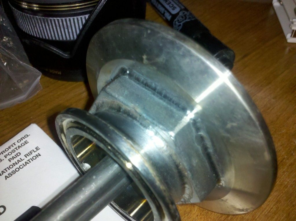
I welded a 1.5" ferrule to the keg then-clamp, 1.5" short ferrule welded to 1"ss nut welded to 2.5"tc cap bored out to clear element hex,clamp, 2.5" short ferrule welded to 2.5" long ferrule,clamp, 2.5" cap bored out to fit appropriate size cord grip (this one was a 3/4" plastic, I'd buy the aluminum if I did it again) Inside I welded a bolt to use as a ground clamp.
The smaller one was 110v and smaller wire, so I used 2" ferrules. I'm sure you could squeeze the 10g wire into the 2" ferrules, but I was more comfortable with the extra room.
I thought about threading the tc cap itself to eliminate the nut, but I don't have my lathe yet...
The clearance is too tight for an element wrench, but it hasn't leaked being hand tight.
You probably should have just posted a parts list.
I was just looking at your element connector, it is very similar to what I was planning. From what I read you used a 1.5" to connect to the keg. What size did you use for the electrical housing? Also what did you use for the electrical connector where it comes out of the cap?
Do you think the size you used is sufficient? If you were doing it over would you go bigger or smaller?
Thanks
Airplanedoc
Well-Known Member
That is perfect, I had been trying to figure out if I wanted 2.5 or 3" to cover my electrical wiring.
Thanks
Thanks
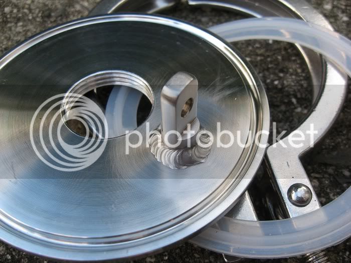
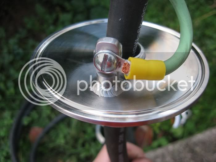
SV_1, just curious but how did you attach the ground cable to the inside of the 2.5" couplers that have been welded together?
I'm not sure how he did his, but here's one way you could do it. This is mine:
thelorax121
Well-Known Member
Nice shot Kevinik, very helpful. What did you use to drill and tap the caps, any problems there?
I'll post up a sketchup model of my first design soon for evaluation, additional scheming...
I'll post up a sketchup model of my first design soon for evaluation, additional scheming...
thelorax121
Well-Known Member
Alrighty, so here is rendition one exploded.
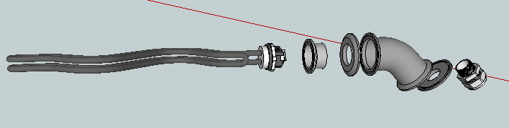
Basically a 2" 45 elbow with one end cap tapped and drilled for 1" NPS (silicon o-ring not pictured), then soldered to the butt weld end of the 1.5" ferrule in front which will connect to the keg. The NPS cap will also have a bolt soldered to it similar to Kevink's design. The opposite end of the elbow has a cap drilled out to to proper OD for a liquid tight cord grip (in this case 1.05"). The elbow will finally be mounted to the keg angled sideways towards the control panel.
I have a tri clamp heat stick that I made previously from a 2" 90 degree elbow with threaded caps, and did not have a problem with the 10 ga wire, so I think this design should leave enough room to work with, but if anyone has any questions, comments of suggestions, please let them fly.
Here is the link to the sketchup file as well if anyone wants to play around with the design. I have modeled a slew of tri clamp components and electrical fittings in all sizes as well, so if you need additional components to work with drop me a line and I will be happy to help.
http://www.mediafire.com/?o6d0o2a6tju1ham
Nice shot Kevinik, very helpful. What did you use to drill and tap the caps, any problems there?
I used a lathe to make the hole and thread the end cap. No problems at all. It cut like butter!
Kevin - I used the new micromark lathe I got for Christmas to cut the hole to 1.200"(I think) , but 1" NPS tap in stainless cuts a bit much, and requires more torque than the three jaw chuck could do without possibly warping the end cap, so started with a 1" NPT tap, then finished with a 1" NPS
thelorax121
Well-Known Member
Technically couldn't you use just the NPT tap and drill it all the way through? I was under the impression that the diameter of NPS was equal to NPT at it's widest point, aka the end of the taper.
From previous page.(btw you guys are overly anal with cleaning. Not a bad thing. At my winery we pressure wash our giant tanks with a heated pressure washer and no chemicals. Just hot water over 200 degrees. It'll kill all bacteria, yeast and spores. Never had a bacteria problem.
off topic I know but;
200 degree wash does not kill many things and I'd bet they add chemicals to the wine to prevent further growth of nasties. Read the label on the wine. Also just being higher alcohol content of wine will make it more stable than beer.
Kevin - I used the new micromark lathe I got for Christmas to cut the hole to 1.200"(I think) , but 1" NPS tap in stainless cuts a bit much, and requires more torque than the three jaw chuck could do without possibly warping the end cap, so started with a 1" NPT tap, then finished with a 1" NPS
I did mine on a South Bend lathe but did not use a tap. I used the lathe's lead screw to advance a cutter to cut the thread.
thelorax121
Well-Known Member
I need a lathe...")
If I had a dime (or lathe) for every time I thought this....
Might just have to plunk down the cash an recoup the cost doing local, small scale machining. A bored mind is the devils playground after all
You can get a nice South Bend or similar American iron for a few hundred bucks on Craigslist very easily. Look around for a few weeks or months to get an idea of what a good deal is. Get one that has some tooling and start playing around. Prices vary depending on condition, brand, and accessories, but you can get something totally adequate for this type of work $500 give or take a few hundred. If you need your money back you can easily resell for what you bought it for, but you will not want to part with it.
Technically couldn't you use just the NPT tap and drill it all the way through? I was under the impression that the diameter of NPS was equal to NPT at it's widest point, aka the end of the taper.
My NPS tap is 0.030" larger at the widest..
You can get a nice South Bend or similar American iron for a few hundred bucks on Craigslist very easily. Look around for a few weeks or months to get an idea of what a good deal is. Get one that has some tooling and start playing around. Prices vary depending on condition, brand, and accessories, but you can get something totally adequate for this type of work $500 give or take a few hundred. If you need your money back you can easily resell for what you bought it for, but you will not want to part with it.
My micromark 7x16 lathe will not go that coarse, I do have a south bend I can get for free from my brother, as he has a larger clausing, but 1000 miles away and no room for it... 2 car garage with blasting cabinet, parts washer, air compressor, stacking washer and dryer, hydraulic press, milling machine, table saw, 8' benches, motorcycle lift, 3 motorcycles, 2 toolboxes hydraulic tubing bender, full-size tig welder, mig welder, gas torches, water heater.. and a big pile of Christmas decorations that I need a place for ;-)
I posted in another triclamp element thread, but wondering if this one might be more appropriate.
I'm using the triclamp element adapters from brewershardware. Everything is hooked up and you can see my full setup here.
My concern is that the element adapter bodies get quite hot when the liquid is heated. The cylindrical part of the adapter, that is. Is this something to be concerned about? Will prolonged exposure to high temps during a boil affect the wiring or the sheathing around the wiring at all? If so, what do you guys do to mitigate this?
I love these triclamp element adapters, but the heat being transferred into the body of the adapter is concerning.
Thanks!
Julian
I think your equipment will be fine, you should not expect to be touching any part of the boil kettle when wort is over 140 degrees, and the materials used in construction can all handle well over 250 degrees without worry...
I think your equipment will be fine, you should not expect to be touching any part of the boil kettle when wort is over 140 degrees, and the materials used in construction can all handle well over 250 degrees without worry...
Cool. That's what I wanted to hear
So based alot on this thread here's the latest design that I have converged to. I basically use 2" triclamp caps and ferrulles to come up with this assembly. I really like that I can break down the entire bit from the keg quickly and easily. The key to making to all happen was to take a single 1" npt stainless couple (I like the machined morebeer ones) and bore to 2" end caps to match the couple. I then tig weld and passivate the new 2 sided 1" coupler. This is the key. I then simply weld up 2-2" TC long ferrules to act as the body. Finally, a 2" end cap is bored to allow for the strain relief and a grounding screw are added.
I included a picture of a diptube I did for my kegs as well. Very similar approach as the heater element.


I included a picture of a diptube I did for my kegs as well. Very similar approach as the heater element.
That design is what I am leaning towards, would like to design it with the clamp closest to the kettle being replaced by draw-screws, and the clamp further away just welded... just looks a little more sano, a little less weight hanging on the keg, and when I or a helper disassemble while cleaning, don't have to worry about opening those..
varocketry
Member
I purchased the 1.5 " ferrule for my 5500w CAMCO and encountered the same clearance issue.
I then found and now use a 2" ferrule from Hillbillystills :
http://www.hillbillystills.com/Heating_Element_plate_p/hecp.htm
This offers the clearance I prefer and had 2" ferrule TIG'ed to my keg.
BTW, my first CAMCO has a short in the black terminating block.... maybe I torqued it incorrectly during my build. I am looking for the THREADS that discuss great looking enclosure box designs to protect the element/wires.
Any links to recommend anyone?
I saw a great COPPERPORN deisgn some while back that I can't find again.
smoothlarryhughes
Well-Known Member
how are you covering the connections when using this? seems easy to install onto the kettle, but the video doesn't show how to cover the connections.
Erbe
Active Member
- Joined
- Jul 27, 2013
- Messages
- 31
- Reaction score
- 1
Still Dragon Seems to have a kit that looks right, placing an order tomorrow, pricing seems fair, just waiting on shipping cost and delivery dates.
http://www.stilldragon.com/element-guard-kit-and-adapters.html
http://www.stilldragon.com/element-guard-kit-and-adapters.html

Similar threads
- Replies
- 52
- Views
- 5K
- Replies
- 25
- Views
- 4K
- Replies
- 0
- Views
- 1K
- Replies
- 7
- Views
- 3K
- Replies
- 8
- Views
- 2K
