All Electric All Grain Brew Rig build in progress, need electrical review

Homebrew Talk - Beer, Wine, Mead, & Cider Brewing Discussion Forum

Help Support Homebrew Talk - Beer, Wine, Mead, & Cider Brewing Discussion Forum:

This site may earn a commission from merchant affiliate links, including eBay, Amazon, and others.

flananuts

Supporting Member
HBT Supporter
Joined
Dec 2, 2008
Messages
506
Reaction score
1
Location
Monmouth County, NJ
Good afternoon and let me first say thank you to all those who took the time to post their DIY projects on this beautiful forum. If I could remember all of your names I would gladly give you credit. However as to not waste time, I'll get this going.

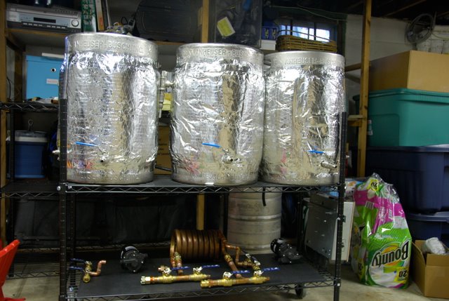
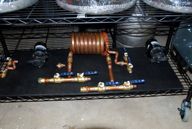
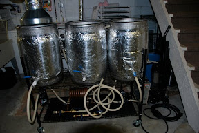
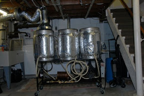
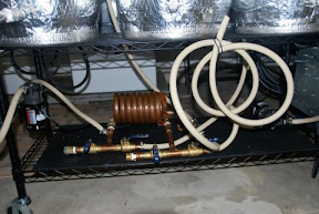
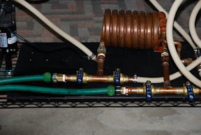
I'm building out a single tier all electric RIMS brew station in my cellar and have sourced a good amount of the parts, including pumps, kettle hardware, however the majority of my time so far has been spent on designing and constructing my controller. Since I'm going to be bringing 110v in to power the PID's and pumps, and 240v in for the 4500w heaters in my HLT and Brew Kettle, this took a lot of research and patience in order not electrocute myself.
First of all, I have a 30 amp GFCI breaker installed in the panel where my old 240v dryer was wired, and I have a separate 110v GFCI as well. All my cable hookups are 3 connection twist lock and will connect vertically into my panel.

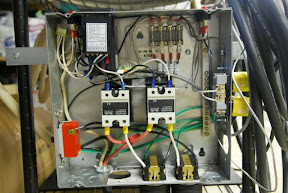
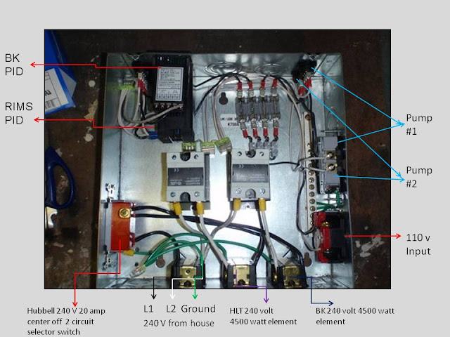
What I request of you with electrical backgrounds is to review what I've done so far and tell me if you see anything glaring or downright dangerous. Note that the HTL and BK will either be SS pots or keggles and the heating elements will be grounded to the pots.

Here's it so far with some labeling, please excuse the 10 AWG white colored wire for my second hot on the 240v.
controller%20pic.jpg


Please let me know what you think. I will continue to post my project as time and wife and job and children permit.

Flananuts
 
I have a question about the power inputs to your panel. If I understand the picture correctly, you have a female outlet for both the 240 vac and 120 vac inputs. This implies that your power cord will have a "hot" male end. If I am understanding this correctly, it is extremely dangerous.
It would also be safer to have a single power input. You could run a 4 wire power cord from your panel to the outlet for your 30 amp 240 vac GFI breaker. You could add a power distribution block (about $25 ebay or surplus) to your panel and run your 120 vac and 240 vac circuits from a single power input.
Obviously, you would need to change the outlet for your 30 amp 240 vac GFI breaker to a 4 prong outlet and the power cord would need a 4 prong male end.
 
Thanks for the response. I see what you mean about potentially having a hot male connection and will definitely hard wire my power connection to my controller and split out the 110 and 240. I do have a follow up question. From an amps perspective my heating elements shouldn't be more than 18amp draw at peak and only one element at a time. I can't imagine drawing more than say 2 amps on the pumps and PID's at max. Do you see any reason why I would run into any problems just pulling power from the 240 vac circuit?

Could I also just bypass this and pigtail one hot and neutral over to my 110 needs

Thanks

Flananuts
 
Worst case scenario:
4500 watt element pulls about 20.5 amps (4500/220)
Each march pump pulls about 1.2 amps
Your PIDs will pull less than 0.5 amps each
Total: 23.9 amps
Well below the limits of your 30 amp breaker. You will be fine.

I am not sure what you mean by pigtailing a hot and neutral. I think adding a small power distribution block with 3 poles (2 hot and 1 neutral) on the input side would be perfect. You will also need a grounding bar for all your grounds.

Here is a distribution block on ebay:
Square D-Distribution Block- 3 Phase- 2/0 to #14 Wire - eBay (item 350154672733 end time Jan-24-09 09:01:01 PST)
 
Thanks for the suggestion and the link to the block. I'm going to make the changes. There is a grounding bar in the box now. I can run both my 110 and 240 grounds to that right, then return ground via my 4 wire connection back to the circuit breaker?

Thanks

Flananuts
 
as long as everything's bonded to the ground via ur 4 wire, ur ok... pigtailing should be fine too... don't see the need in a distribution block with that small of wire.
 
Worst case scenario:
4500 watt element pulls about 20.5 amps (4500/220)
Each march pump pulls about 1.2 amps
Your PIDs will pull less than 0.5 amps each
Total: 23.9 amps
Well below the limits of your 30 amp breaker. You will be fine.

I am not sure what you mean by pigtailing a hot and neutral. I think adding a small power distribution block with 3 poles (2 hot and 1 neutral) on the input side would be perfect. You will also need a grounding bar for all your grounds.

Here is a distribution block on ebay:
Square D-Distribution Block- 3 Phase- 2/0 to #14 Wire - eBay (item 350154672733 end time Jan-24-09 09:01:01 PST)
I wouldn't say your total current draw is WELL below your limit. You'r drawing 23.9A where 80%(recommended limit) of your breaker is 24A. Still within limit safely, I wouldn't go adding much more thinking you've got tons of room to play with.

It'd also be easier to fully examine the circuit with a schematic. I don't personally know the connections to those components from looking at them. Some may through experience with them though.
And I agree with the Male plug carrying the 240V. Scary stuff. you bump into the plug hanging there, OUCH! actually you might not feel anything:(
Have you thought of using a manual lever on/off for the sub panel as well?
 
I understand the schematic request, and if I had the time and know how I would. The toggle switch to the bottom left is a 2 cicuit center off 240v Hubble switch. So If the switch is in the off position and the PID's are off, neither of the hot leads have the potential of being hot. Regarding the two males, I always intended the male to the controller to be always plugged in, but removeable for storage and breakdown. I do plan to change that based on the comments to my design( thanks!). Regarding the draw, the 20amps on the heater would only be at full draw which I don't imagine I would be at, more like 17-18 amps drawn when under load.(but then again, I sell video ad technology and am self taught on electricity)

Flananuts
 
It's been a while since I added to this thread. I wanted to post some pics of where the rig is as of this morning. It's definitely coming along and will be done sooner than I thought. I take no credit for any originality in this build. It's totally constructed based on all the great ideas from virtually everyone on this forum with a lot of thought on my part. Please feel free to share thoughts or ideas or criticism(constructive only please)
DSC_0052.JPG


Close up of pumps, heat exchanger/chiller and valves
DSC_0053.JPG


Thanks for looking
 
I am not an electrical guy by any means, but have been contemplating converting my two tier Three keggle system to electric by adding a 4500 watt heating element to both my HLT and my Brew kettle and then running them off of a ranco hooked op to a very simple control box I found at Highgravity. What would the diference between all the work you did and what I am talking about be? Would it be a matter of control? I am just trying to keep it simple is all, but I don't want to buy a bunch of stuff only to have to rebuild something.
 
My only question is why do you feel it necessary to control the temperature of the wort in your boil kettle with a PID? There is no pressure so the maximum temperature of your wort in the boil kettle is 212*. It would seem more logical to want to control the temperature of your strike water or sparge water in you HLT.
 
You don't control the temp with the PID, you control the boil. The control is on manual at all times. When boil starts, you drop the output to 60-70% to maintain a nice steady boil. Saves on electricity and saves beer! The RTD is there because the PID won't work without it.
 
You don't control the temp with the PID, you control the boil. The control is on manual at all times. When boil starts, you drop the output to 60-70% to maintain a nice steady boil. Saves on electricity and saves beer! The RTD is there because the PID won't work without it.

Bingo... RTD or K type... either way, the PID needs a temp input so that it doesnt go into an ERROR mode.
 
Just trying to learn some basics for the future here. So, If the PID is set to manual, you can tell it to run at a percentage of full output rather than a set temperature?
 
Just trying to learn some basics for the future here. So, If the PID is set to manual, you can tell it to run at a percentage of full output rather than a set temperature?

Correct...but the PID NEEDS the connection with the TC to run at all. It completes the circuit, even though the values (temp) coming from the TC are disregarded and the PID controls the percentage of time the element is on, pulsing in quick bursts to acheive an adjustable load (power %).
 
Correct...but the PID NEEDS the connection with the TC to run at all. It completes the circuit, even though the values (temp) coming from the TC are disregarded and the PID controls the percentage of time the element is on, pulsing in quick bursts to acheive an adjustable load (power %).

Thanks. That is my piece of knowledge learned for the day! ....Just another six months one bite at a time and I will get there! :D
 
You don't control the temp with the PID, you control the boil. The control is on manual at all times. When boil starts, you drop the output to 60-70% to maintain a nice steady boil. Saves on electricity and saves beer!

Understood, but isn't more critical to to brew to get the strike and sparge temperatures on the money rather than control the boil? The answer may make me rethink controlling the HLT temp on my rig.

The RTD is there because the PID won't work without it.

No kidding.;) I use a K thermocouple on my rig.
 
Understood, but isn't more critical to to brew to get the strike and sparge temperatures on the money rather than control the boil? The answer may make me rethink controlling the HLT temp on my rig.

Totally agree Sawdustguy, I'm in the planning stages on my build. It will be a two-tier all electric most likely. In ThePol's thread, there were some questions along those lines and someone said that they put the thermocouple in the HLT (as I plan to do) and use a switch to switch the PID command from the HLT to the BK when they go to boil. This is what I plan to do, and it makes perfect sense as you say, who cares what the temperature of the boil kettle is (especially as the OP is using a CFC and not an immersion chiller).
 
Sawdust, the sparge and mash temps are more critical. I use electric to control both of those automatically. Since I had a control, all I have to do is switch pots after the sparge and now I can control my boil with the same controller. Just need another RTD or T/C and another element...
 
Sawdust, the sparge and mash temps are more critical. I use electric to control both of those automatically. Since I had a control, all I have to do is switch pots after the sparge and now I can control my boil with the same controller. Just need another RTD or T/C and another element...

Thats why I made my origional comment. I thought it would be better for the OP to use the second PID for controlling the HLT to get the strike and sparge temps on the money instead of controlling the boil.

It would seem more logical to want to control the temperature of your strike water or sparge water in your HLT.
 
I finally sourced both my RTD and K type thermocouple for the rig and will be finishing the assembly for leak testing etc. I realized after the fact that I didn't actually need to use a temp controller for the BK, but went with it anyway. It is not actually a PID on the BK. There is a PID that is measuring temp of the wort via RTD in thermowell upon entry back to the MLT and controlling the heating element in the HLT. I will likely have to use a thermometer in the HLT through the sight glass for hitting strike and sparge. I need to think about this some more after I get this thing leak proof.
 
I wanted to post an update on the all electric basement brewery. My SWMBO politely asked as I was heading off to buy a 7 cu ft freezer off Craigslist how much I've spent on all this so far. My response as should be everyone's, " a lot less than if I bought if prebuilt, and yes honey go buy whatever you want."

I've got a small issue I think with a March pump leaking some voltage back to the panel and tripping my 30a 2 pole GFI thanks to HomeBrewTalk.com forum for helping to diagnose.

Here are pics of the updated rig with ventilation hood in place over BK. I encourage your feedback and comments outside of the obvious YES THIS IS OVERKILL. If I had a hot rod or muscle car to work on I probably would be just using a cooler and a banjo burner but I digress. T minus 6 days until brewing. What should I build next?

DSC_0284.JPG


Picture with the vent hood in place
DSC_0279.JPG


A shot of the pumps and heat/cool exchanger. The hose connections are also a great way for flushing the copper coil and filling up kettles for cleaning.
DSC_0281.JPG

DSC_0286.JPG


Picture of the control panel without the cover on
DSC_0300.JPG


My brewers apprentice
DSC_0293.JPG

DSC_0292.JPG
 
Looks like you are going to get a lot of moisture built up in the drooping vent hose. The more moisture, the heavier, and more drooping. Not to mention mildew.
 
Thanks for the advice there, nothing a little line and foil tape can't fix. The blower is over 500cfm and will practically create a vacuum on the BK when set right on top. I've wet run this thing and had temps up past 168 deg for more than an hour, the vent works real well. My dehumidifier wasn't working any harder during my tests so hopefully I won't have any real issues with moisture buildup in the basement. Mildew and mold are bad!
 
Back
Top