Aubers Contactor

Homebrew Talk - Beer, Wine, Mead, & Cider Brewing Discussion Forum

Help Support Homebrew Talk - Beer, Wine, Mead, & Cider Brewing Discussion Forum:

This site may earn a commission from merchant affiliate links, including eBay, Amazon, and others.

Beeskneesbrew

Well-Known Member
Joined
Mar 15, 2011
Messages
128
Reaction score
3
Location
Des Moines
Does any one know how you hook up the coil portion of the auber contactor? From the looks of it there really isnt an input or out put side? Any pictures or diagrams would be very helpful.....Thanks

Matt
 
Here is where I currently stand....


ForumRunner_20120616_165957.jpg
 
The polarity doesn't matter. Bring your hot to one side and neutral to the other.
 
Kinda new to this electric brewery hung, so I'm just wondering, what are all the ssr's for, is tha a bcs rig, or your "standard" 1 2 or 3 pid panel build, I have 3 pid's but only 2 ssr's. I've seen a couple now that have 6 ssr's and can't figure out why there are so many! Please help me!!
 
It is a Bcs rig, I have 3 heating elements( hlt,bk, and rims) along with 2 pumps and the 6th is for the 5v bcs plug.
 
Does any one have any photos of how theirs are hoked up? I'm curious on how hooking the coil up with my neutral wire to others coils is done.

Thanks,
Matt
 
That looks fine above, the white is the neutral, and you still haven't hooked up the hot To the other side of the contactor from the switch correct?
 
View attachment 65222


This is how it is done ad of now, don't know if it is correct.
Matt,

I'm not sure that you understand the connections on the contactor. It appears that your wiring so far is correct for the contactor coil. The coil input is wired to the front and the back of the unit.

The power that the contactor is controlling is delivered to one side (as shown on your wiring) and the contactor output is delivered from the other side (out of the top 2 connections in your image. What has me concerned is it does not appear that you have enough room at the top on the contactor to make the 2 additional connections for the output side.

Here is a sketch up of how it might be wired (using 120V for the coil and for the power delivered).

Contactor-wiring-120V-2.jpg


I hope this makes sense and helps you.

P-J
 
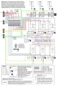
PLEASE REVIEW MY WIRING! Let me know if there is anything I have missed, the top row of switches are not finished yet. I still need 3 sets of additional N/O contacts.

Thanks,
Matt

ForumRunner_20120618_233227.jpg
 
In my opinion, the contactor is very important. I want a way to definitely cut the power to the elements. Putting in contactors between the SSR and the elements means I can leave the PIDs powered up and turn the elements off. Also, SSRs are solid state devices - silicon. When they go bad they usually go bad closed allowing high amperage power to flow through them. Without contactors you would probably have to throw a breaker either in your CP, sub, or main panel to turn the power of.
 
Back
Top