240VAC Toolbox Control Panel with Pics

Homebrew Talk - Beer, Wine, Mead, & Cider Brewing Discussion Forum

Help Support Homebrew Talk - Beer, Wine, Mead, & Cider Brewing Discussion Forum:

This site may earn a commission from merchant affiliate links, including eBay, Amazon, and others.
Joined
Apr 23, 2009
Messages
37,058
Reaction score
17,821
Location
☀️ Clearwater, FL ☀️
I built this on Father's Day to replace a super ghetto metal box. I had gone with the metal because I thought I could use the case as a heat sink for the SSRs, but that didn't turn out to be such a good idea (box got hot, PID did not like that) :( The metal is hard to work with, and the result was not pretty.

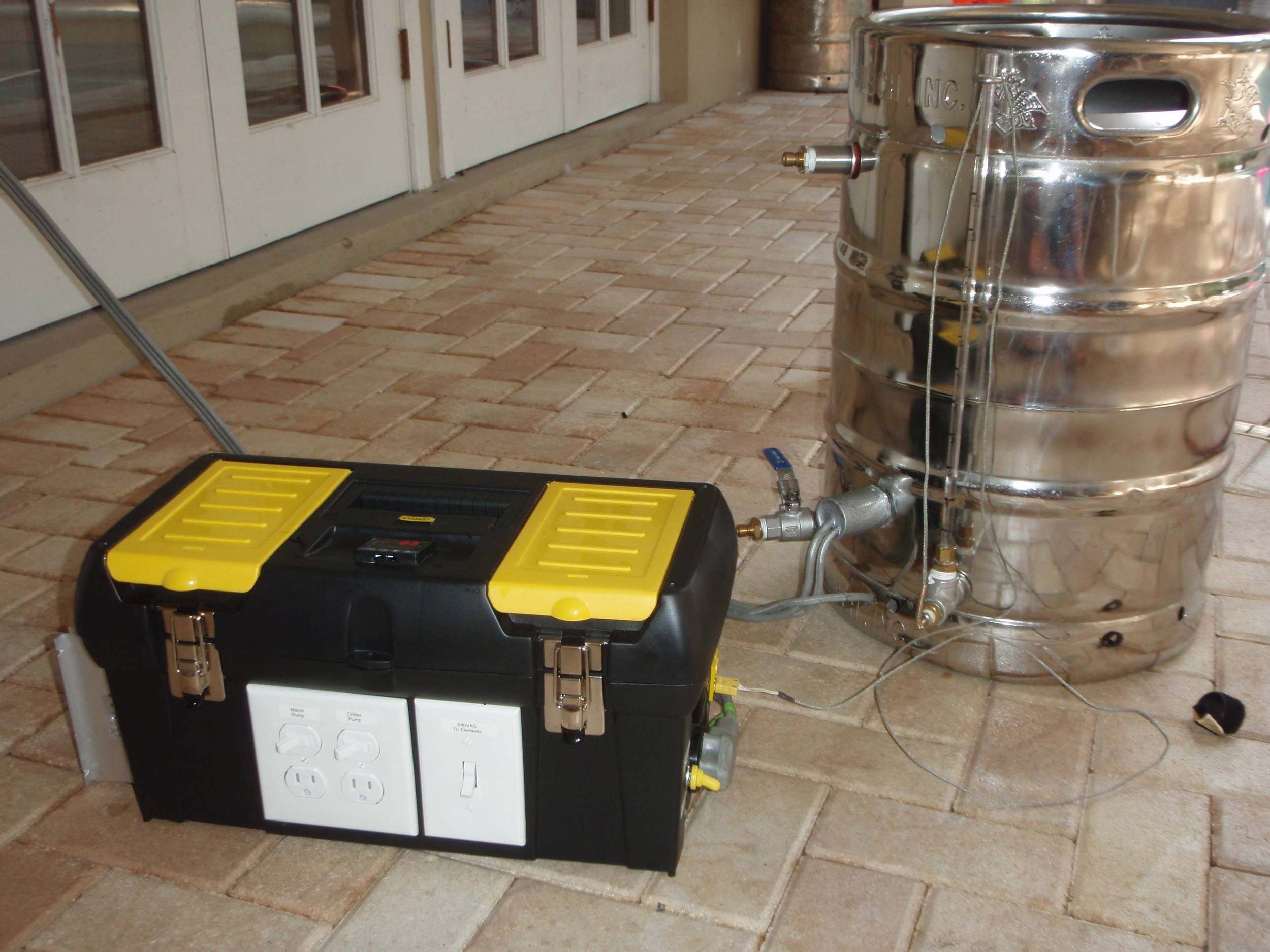
I saw someone else on this forum make a box similar to this one (probably the same exact box, but I can't find that thread). This toolbox was $9 at Lowes (or HD). I used a dremel with little cutoff wheels for all square cutouts. Round ones were either drill or hole saws.

One thing that makes this box unique is the single PID to control two elements. I have a 3P3T switch that selects which element and thermocouple is being used; the switch has a middle position that selects neither (both off). Because of amperage limitations, I can't run two elements at the same time, so there was no point in 2 PIDs, In fact, If I used 2 PIDs I would probably trip the breaker all the time by accidentally turning both on. This design eliminates that problem. There's an attached schematic in PDF/ZIP for anyone interested.

Two important things to mention here: 1) Although the schematic shows a 4 prong outlet supplying this box, I only have a 3 right now. Soon to be corrected. 2) I'm running thermocouples through a switch. This will create some error due to the way thermocouples work (I do use thermocouple wire tho). Quick testing showed maybe a few degrees, but I have to test more. Probably will switch to thermistors or RTDs.


toolbox_pid-41332.jpg

toolbox_front_panel-41328.jpg

toolbox_24vac_plugs_and_switch-41327.jpg

toolbox_heatsink-41330.jpg

toolbox_guts-41329.jpg


View attachment Brewing Control Panel Schematic.zip
 
I like it, nice and compact! Are you using a GFCI Breaker with this? Have you been able to brew with it yet?
 
I love the 240 in a box setup. I am looking to do the same thing by running an extention from my dryer outlet. What type of extention wire/cord did you use from the house to the box? How much does that stuff cost? I thought it was pretty pricey, and I am needing at least 25', preferrably longer. Just hoping it doesn't become cost prohibitive.
 
Nice, looks like the box I picked up at Target for my portable RIMS. I think I got it for a little under $10 on clearance.

32059_449164853272_602223272_5728220_3567487_n.jpg


What did you use for the text you put on the switches?
 
This is cool.

+1 on 10AWG wire...though the more I zoom, the more it looks to be 10 gauge.

I see that you put your switch to the elements after the terminal blocks. Any reason why you decided not to put it before the whole circuit, kind of like an e-stop?

How hot does this get?
 
Are you actually using the BK to heat water to some specific temp at some point during the session, or are you just boiling in it?
 
I like it, nice and compact! Are you using a GFCI Breaker with this? Have you been able to brew with it yet?

I put a 30A 2-pole GFCI in my breaker box.

I just finished this box last night. Electrically, it is almost identical to my last crappy box, which I brewed with at least 20 times, so I know the schematic is sound.

what size wire are you using? it looks pretty small (12 gage ?).

Mostly 12 gauge solid core. I had 10 gauge before, but I like the solid better for routing. 12 gauge is fine for chassis wiring of 25A.

any pics of the heating element mounting?

Glad you asked (I think this is what you are looking for... click on thumbnails for bigger pic)

p6280002-41336.jpg

p6280001-41335.jpg


What type of extention wire/cord did you use from the house to the box? How much does that stuff cost? I thought it was pretty pricey, and I am needing at least 25', preferrably longer.

30A dryer cord from Home Depot. It is about 6' and cost about $10 (I think). It's probably 10 gauge. This is fed through my attic from my breaker box, probably about 50'. At least. I probably lose 75W over that length.

looks like the box I picked up at Target for my portable RIMS ... What did you use for the text you put on the switches?

Yes, looks like same box ... Brother P-Touch labeler - I use it for everything.

I see that you put your switch to the elements after the terminal blocks. Any reason why you decided not to put it before the whole circuit, kind of like an e-stop? How hot does this get?

That's a good point about the switch. My intention was to be able to turn off all power to elements, which it does. I don't want to turn off power to the PID, so it will probably stay where it is.

I ran a quick test this morning and the inside of the box hardly got warm (I just ran about 5 gallons of water to boiling). I was really surprised. I had considered a fan, but I don't think it needs it (yet). I need to do some real testing. I finished the wiring last night!

Are you actually using the BK to heat water to some specific temp at some point during the session, or are you just boiling in it?

BK only boils. HLT uses PIDs auto mode, then I have to set the PID to manual for BK PWM mode. I sense there is some underlying second question here, but I can't guess what that is.
 
BK only boils. HLT uses PIDs auto mode, then I have to set the PID to manual for BK PWM mode. I sense there is some underlying second question here, but I can't guess what that is.

If you are only using the manual mode on your BK, then you don't even need a temp probe in the BK. The PID needs a probe connected to it to work (I think), but in manual mode the probe could be anywhere.... doesn't need to be monitoring the BK at all.

That would save you the error introduced by the Probe selector switch. You can just leave the HLT probe hard-wired to the PID at all times.

edit: unless, of course, you intend to monitor the BK temp during chilling via the PID display. If so, you can ignore my rantings. :D

You are right on everything you said. A connected sensor is necessary (or the Auber PID won't output), but it doesn't serve any useful purpose except to see the temp of the chilling wort. I'm going to brew this wkend and I'll see how much error the switch adds. It was within a few degrees from ambient to boil this morning, which was a surprise.
 
yeah... if you are off by a static amount, then you can just program the PID to take that offset into account and you'll be good to go.
 
yeah... if you are off by a static amount, then you can just program the PID to take that offset into account and you'll be good to go.

That is what I'm hoping for, an offset.

[edit] just changed my PID offset by 5 degrees (from +3 to -2.5); both sensors read exactly correct at 165. They'll be off at ambient and boil, probably, but I'm not too concerned about that
 
OK, some temp testing. I ran the box for about an hour. Kept about 5 gallons of water at 165F. March pump was also running, circulating water. Temp sensors are dialed in.

Infrared temp gun says the heat sink is only at 85. I opened the box and there is no detectable heat at all in there. Infrared temp gun says 82, which is ambient. Once again, I'm surprised and tentatively calling my box a win. I win.

Also, ScubaSteve above mentioned an Emergency Stop switch. I have something similar that I plug into. This:

240V_power_switch.JPG
 
Nice!

I would check the temp while boiling full-on. The SSR barely gets used while maintaining mash temps for me, so the SSR never gets too hot at that point.

During the boil, it gets really hot. I need to add a fan or two to the thing.
 
I put a 30A 2-pole GFCI in my breaker box.

I just finished this box last night. Electrically, it is almost identical to my last crappy box, which I brewed with at least 20 times, so I know the schematic is sound.

Mostly 12 gauge solid core. I had 10 gauge before, but I like the solid better for routing. 12 gauge is fine for chassis wiring of 25A.

Glad you asked (I think this is what you are looking for... click on thumbnails for bigger pic)

that's what I thought....not to be a party pooper, but not only is that that against code (depending on how "code compliant" you want to be :p) it's also a fire hazard. 12gage is only good for 20A and much be protected as such. If you have a 30A breaker it must be 10gage. The breaker is there to protect the wire and that's it. If you're running 25A on 12 gage standard wire (90*C rated) you will probably degrade it over time and break down the insulation...that's not a "free air" installation. I would use all 10 gage. better safe than cheap.

Thanks for the pictures...that's exactly what I was looking for. :mug:
 
I gotta post pics of mine, looks very similar

Its got a BIG heat sink that takes up about 1/3 of the box for the two SSR's
 
that's what I thought....not to be a party pooper, but not only is that that against code (depending on how "code compliant" you want to be :p) it's also a fire hazard. 12gage is only good for 20A and much be protected as such. If you have a 30A breaker it must be 10gage. The breaker is there to protect the wire and that's it. If you're running 25A on 12 gage standard wire (90*C rated) you will probably degrade it over time and break down the insulation...that's not a "free air" installation. I would use all 10 gage. better safe than cheap.

It's about a foot of 12 AWG wire. That'a about a milliohm - i^2R heating is very, very minimal. Not in conduit. Fire hazard - seriously?

Chassis wiring rules (I assumed :confused:) are for exactly this type of application. Regardless, I'll to a full boil test later and check temps.
 
It's about a foot of 12 AWG wire. That'a about a milliohm - i^2R heating is very, very minimal. Not in conduit. Fire hazard - seriously?

Chassis wiring rules (I assumed :confused:) are for exactly this type of application. Regardless, I'll to a full boil test later and check temps.

yes, seriously...that's why I pointed it out. the heating is regardless of length...if you have 100' it's still only milliohms/foot (probably more like micro)
 
yes, seriously...that's why I pointed it out. the heating is regardless of length...if you have 100' it's still only milliohms/foot (probably more like micro)

I don't know how much real world experience you have, bjorn, but you're off base here. Dissipating a few watts of heat into my box is not a fire hazard. So stop waving your hands in the air.
 
I think his point is that your breaker will allow 30A through, but your wire is rated only for 20A. Running 29A through it would cause a problem, yes?
 
I'm conducting 23A (5500/240). 1.5mohm/ft, I'm dissipating about 1.5W over a 2 foot section. That is nothing.

12 AWG wire is rated for 41A for chassis wiring.

I've done the math. The wire is sufficient for the application. I've measured the temps. It's fine for the application.
 
12 AWG wire is rated for 41A for chassis wiring.

Ah... I wasn't aware of that.

This was one of the things I had the most trouble figuring out when I was building. Everywhere I looked, I seemed to find different ampacity ratings for various gauge wire.

Rather than beat my head against the wall trying to get it nailed down, I just used the most conservative ampacity rating I had come across and rolled with it.
 
How much heat you're dissapating has nothing to do with it. The wire will heat up, we know that, and as is does it also heats up the terminal block it's connected to and the breaker, and relays and everthing else; not by heating up the air around it, but by the direct connection between them. That's were the limitation is. The terminals you're using, the breaker, the relays, etc. and I'm sure the enclosure is only rated for a certain temperature (typically 75C). If it exceeds that, you're risking premature failure of those components (read: fire risk).

It doesn't matter if you're only drawing 23A through it or that the wire can handle 41A, the fact is that it has the ability to have 30+ amps drawn before the breaker trips. If there is a fault and more current is drawn for an extended period of time, the problem arises. This is why NEC and every other code has limits on breaker size vs wire size to keep the temp rise to an acceptable level. Like I said, the breaker is to protect the wire and limit the temperature rise so there is no risk. By the way, the wire you're using may have a 41A rating, but I bet that's at 105C...way more than a breaker or terminal block can handle.

I'm an electrical engineer (w/a masters degree) and deal with currents/wire size every day, but you don't have to listen to me. Just trying to keep you safe.

Good luck :mug:
 
So I guess sticking some 10 awg in there would be slightly more expensive for the small amounts used..but will definitely prevent forest fires. So, if I understand correctly, you'd only need 10 awg in the path of high current on its way to the element. Other than that, 12 awg can be used for "normal" current, like the PID, 115v receptacles, etc.....
 
+1, I'm a little confoozed myself and don't want to catch my expensive electronic components on fire when I put them together.
 
I boiled for an hour (PID = 100%). SSR got up to about 135F, inside of box got to about 90F, highest wiring temps got to about 115F.

Ambient is about 85 right now in sunny florida.

Damn, wish Japan won against Paraguay.

Did you do the boil with the box open?

On another note, let's try to keep this civil. Anyone building something like this is taking a risk. It's clear that you should err on the side of caution if unsure....

Passedpawn: Do you think the plastic box is better than a metal toolbox, a la "simple brewing"?
 
Civil is good ScubaSteve! I think we're all taking a risk boiling large amounts of sugar water, and some of us still use glass carboys to ferment in. Let's keep in mind that we're all (legally) adults and we can make our own decisions as to what is safe enough for us. To each their own I guess...

I'm planning on using a 50 cal Ammo Can for my box, but I want super duper durability, portability & something that's watertight in the end.
 
Yeah, I thought real hard about that....then I wonder if I really want a watertight (and probably airtight) box. Ventilation is a good thing Plus it'd be a real PITA to cut.
 
Did you do the boil with the box open?

On another note, let's try to keep this civil. Anyone building something like this is taking a risk. It's clear that you should err on the side of caution if unsure....

Passedpawn: Do you think the plastic box is better than a metal toolbox, a la "simple brewing"?

Boiled with the box closed. After more than an hour, I cut power and immediately measured temps (with an infrared temp gun) and also reached into the box and felt the wires, terminal blocks, etc. Nothing was hot at all.

I love the plastic box. Love love love. The metal box was a major pain to build and, in the end, felt a little clunky. I was concerned that the plastic wouldn't take the heat of the heatsink, but in testing this wasn't an issue. I considered adding a fan after I tested it, but I now see I don't even need that.

I'll be brewing 1 (maybe 2) batches this wkend. If there is anything else to add, I'll post here.

Yep, steve, err on the side of caution is great advice. BTW, did you look at my schematic? Do you see how I'm using the one PID for both elements?

[edit]

Here's the old crappy one. This one had 10 AWG wiring. I hated this thing, although it worked well.

Old_Metal_Control_Box.JPG
 
Yeah, i read the schematic. I appreciate you listing the digikey part numbers ;) I'm looking real hard at doing this for my rig...it just seems like it'll be at LEAST as expensive as buying an enclosure, plus I'll be able to move the box to compensate for the short 220v cord.
 
I'm not sure where the chassis wiring comes in [citation needed]...NEC doesn't acknowledge it (that I can find or to my knowledge).

As far as general wiring is concerned we have to keep the temperature of the wiring under 75*C so as not to exceed the terminal block, breaker, relay, etc ratings. In section 310.15(B) (Article 310: Conductors for General Wiring), it says to refer to tables 310.16-.19. The table that we would use is 310.17 (free air at 30*C). The max ampacity for #14 is 25A, #12 is 30A, and #10 is 40A. However, all of these have a asterisk next to them saying to refer to section 240.4(D) in which is states the maximum over current protection device (OCPD) for these conductors must be 15A, 20A and 30A respectively. If you have 23A load current you need a 30A OCPD (23*1.25 = 28.75A so you go to the next higher which is a 30A breaker). With a 30A breaker you need #10 wire for you general wiring.

Again, it has nothing to do with the length of the run, but more to do with the conducted heat from conductor to component. And this is all at MAXIMUM CONDITION (think fault conditions, not just normal boiling). Really, what the temp is when you're just running it normal doesn't have any bearing on the temperature/current you should rate your wiring for.

Hope this helps.
:mug:

PS Was I being uncivil? I apologize if I came off that way...not my intention.
 
Nope...you were quite civil. I just didn't want to ruin an awesome thread, and I hoped to keep it from escalating.

My next question is about those SSR's; the SSRD's are about $36 without heatsinks....but I can get two 40A SSR's with heatsinks for ~$10 a piece. With dual ssr's I guess you're paying for a compact build...but how much more space would 4 ssr's take up? I assume the heat output would be the same....perhaps it would be handled better through 4 heatsinks? Or, would it be cheaper to buy a bigger, more streamlined heatsink and hook 4 ssr's without heatsinks (even cheaper that way) up to that one main heatsink?

I hope that makes sense....
 
My understanding is that with the larger SSR's (40A vs 25A) you'll generate less heat, I took a look at the 40A dual SSR at digikey and it's like $77.
 
I'm not sure where the chassis wiring comes in [citation needed]...NEC doesn't acknowledge it (that I can find or to my knowledge).

As far as general wiring is concerned we have to keep the temperature of the wiring under 75*C so as not to exceed the terminal block, breaker, relay, etc ratings. In section 310.15(B) (Article 310: Conductors for General Wiring), it says to refer to tables 310.16-.19. The table that we would use is 310.17 (free air at 30*C). The max ampacity for #14 is 25A, #12 is 30A, and #10 is 40A. However, all of these have a asterisk next to them saying to refer to section 240.4(D) in which is states the maximum over current protection device (OCPD) for these conductors must be 15A, 20A and 30A respectively. If you have 23A load current you need a 30A OCPD (23*1.25 = 28.75A so you go to the next higher which is a 30A breaker). With a 30A breaker you need #10 wire for you general wiring.

Again, it has nothing to do with the length of the run, but more to do with the conducted heat from conductor to component. And this is all at MAXIMUM CONDITION (think fault conditions, not just normal boiling). Really, what the temp is when you're just running it normal doesn't have any bearing on the temperature/current you should rate your wiring for.

Hope this helps.
:mug:

PS Was I being uncivil? I apologize if I came off that way...not my intention.

Here's where I got my numbers (for better or worse). There are good links there to some of the standards. The chassis wiring (I assume) comes from the handbook referenced at that site and not the NEC.

You're right about the breaker requirements. I don't understand allowing 30A in 12 AWG, but then also requiring a 20A breaker.
 
You're right about the breaker requirements. I don't understand allowing 30A in 12 AWG, but then also requiring a 20A breaker.

ex) If you were wiring from, say a transformer secondary to full wave bridge power module, then you could utilize the full 30A. The protection would be on the primary side. The 30A can be realized if no immediate upstream protection is required.
 
Back
Top