Troubleshooting first electric build, no power to element?

Homebrew Talk - Beer, Wine, Mead, & Cider Brewing Discussion Forum

Help Support Homebrew Talk - Beer, Wine, Mead, & Cider Brewing Discussion Forum:

This site may earn a commission from merchant affiliate links, including eBay, Amazon, and others.

sablesurfer

Supporting Member
HBT Supporter
Joined
Jul 21, 2013
Messages
1,317
Reaction score
305
Hopefully there haven't been too many 'what's wrong with this' threads, because I need to ask what is wrong. :eek:

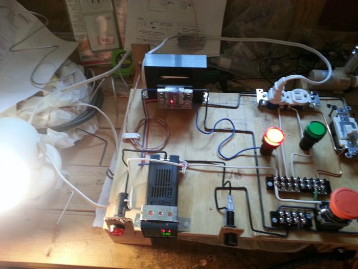
I have built out my first electric control panel and I managed to get past the first power on test without losing any magic smoke. The problem I have now is that while the system indicates that the SSR is switching and that there should be power to the element plug...my test set up isn't working right.

ebrew_board.jpg

In the picture I have two items plugged into the outlet to test the system. The outlets are separate because I have pulled the tabs off them so they are each powered independently. Both plugs have their own indicator lights to show if they have power/circuit closed. The plug on right is my pump power and has the light switch for on and off. The power strip to the far left is plugged into that and you can see that it's indicator light is on.

The problem is the plug on the left, that will be my heating element outlet. It has power coming directly from the SSR and the SSR is wired into the power bridge. The plug in that outlet is the desk lamp over on far left. That lamp never comes on. The LED on the SSR will light, the PID appears to be showing output (see other thread about panel not being labeled right), and the indicator light does fluctuate and get brighter when the SSR appears to be on.

My test have been to lower the set point to about 85 degrees. The RTD is sitting about 76 in basement. I can see the PID and SSR cycling. Then when I breath on the RTD so that it gets up over 86 degrees the cycling stops. It comes back on again as the temp drops. That whole time the desk lamp never lights up.

I found this on youtube, and seems he was trying same thing. Test the system before hooking up to the actual brew hardware. To me it says that my approach to testing should have worked.
( )

Can anyone help?? Would love to finally get this project wrapped up.
 
Last edited by a moderator:
This may sound kinda stupid and I don't want it to sound condescending, but have you checked the lamp bulb to make sure its not a simple problem like that? I do remodeling for a living and I can't count how many times a customer says "I just can't figure out why this light is not working", I change the bulb but tell them it was a loose wire or something so not to make them feel stupid. If I were you I would use a multimeter for any tests on this system, a light bulb will work for a wide range of voltages where your electronics need 110-120. It will also help to isolate problems with neutrals and such.
 
Nope, I should have mentioned that. I have unplugged it from board and into wall half dozen times as I constantly wondered if I even had the lamp turned on. :D It has a switch on the cord and every 5 minutes or so doubt would set in. So, yes I have tested the lamp itself plugged straight into wall.
 
Interestingly...and this is where my complete lack of electricity math skills comes into play...if I run a quick jumper wire from the left outlet to an open neutral then the desk lamp lights. ?!? The red indicator light does not light anymore (even though still connected).

What I was wanting was to indicate when the elements were actually on...when they were heating. But it seems (???) the LED indicator is my problem somehow. If someone could put it in very simple layman's terms, I might be able to re-arrange and still achieve what I need?
 
Ok, so messing with any project just like I program..."wonder if". Since jumpering around the indicator light made the desk light fire. I tried to figure out how to get the indicator light to work, but move it out of the line of the outlet circuit.
This temp work around appears to do the trick. I have desk lamp lit and indicator LED. They both turn off when the SSR LED turns off.

So...question...I am assuming it is ok to run the indicator and the power to outlet in parallel like this? I wouldn't be drawing too much power away from the element in the end?

ebrew_board_v1-1.jpg
 
Ok, upon your further explanation and looking at first picture again I see your problem. You are putting the led lamp in line with the 12v input to the SSR, essentially dropping that current by the power usage of the lamp. Ohm's law states that w/v=a, using its watts at that low of voltage is dropping it enough that the SSR is not recognizing it. Try putting it inline after the SSR in the 120v line, less drop and the element won't even notice.
 
Ok, upon your further explanation and looking at first picture again I see your problem. You are putting the led lamp in line with the 12v input to the SSR, essentially dropping that current by the power usage of the lamp. Ohm's law states that w/v=a, using its watts at that low of voltage is dropping it enough that the SSR is not recognizing it. Try putting it inline after the SSR in the 120v line, less drop and the element won't even notice.

To me it looked like he had the LED in series with the lamp in the first picture, then swapped it out to parrell in the second. both times it is on the 120V side of the SSR.
Not thinking too much into this response so anyone feel free to rip it apart, but remember that an LED is a diode and will only pass current in one direction, therefore the first picture setup would have cut half the AC sine wave of the output (i.e. power on for only half the time but really fast so you don't really notice it).
I don't know why this would stop the lamp from working though, I would expect that it would only be not as bright. Only thing is if the filiment was not able to get hot enough, but I find that unlikely :confused:

sablesurfer - do you have a wiring diagram that you are using for this build, it would be much easier to trouble shoot what is going on with that compare to photos that can be a bit unclear of what is actually going where sometimes.
Cheers!
 
To me it looked like he had the LED in series with the lamp in the first picture, then swapped it out to parrell in the second. both times it is on the 120V side of the SSR.
--------------------
sablesurfer - do you have a wiring diagram that you are using for this build, it would be much easier to trouble shoot what is going on with that compare to photos that can be a bit unclear of what is actually going where sometimes.
Cheers!

I will have to scribble something up. It turns out that in a real test of the pump it fails the same way. I can only assume because I also have that indicator LED in series with the pump outlet. :smack:
 
Wire your indicator lights in parallel with the load.
 
That will be fun the first time there is a real need to slap the e-stop button and you lay your hand right on those terminal strips with mains running through them.

Also, I agree with jeffmeh. See below for what the diode does to the voltage through your lamp.

5176f4bfce395f3a61000000.png


However, you should still be able to run the lamp on this chopped voltage, you would just need double the wattage of bulb to get the same light output...
 
That will be fun the first time there is a real need to slap the e-stop button and you lay your hand right on those terminal strips with mains running through them.

HEH. Yeah, I am a perfect example of why people should not mess with electricity without supervision. When I started trouble shooting. I started thinking through all the circuits...tapping each part as I thought through it.

Yes.

Tapping.

With my...finger. Felt it in my elbow.

(This is why I started at 110 and not 220.)

No diagram tonight, long day at work trying to get caught up on everything from a week off.
 
Circuit. Be warned it is in NO WAY similar to any of P-J's fine drawings.

View attachment 148815

Ok:
1) is your E-stop switch rated for the total current going through the system?
2) The alarm/buzzer is not working because the alarm out on the PID is a relay contact - you need to pass power through this to the alarm/buzzer and then tie the other side to nuetral.
3) The LED should both be run in parrellel with the loads - They will be restrciting the cureent that can flow through the outlet if they are in series, i.e. the pump/element will be getting power just not enough to notice (P = IV and you are restricting the I and most of the voltage will be dropped over the LED leaves you with not much power for the element/pump)
 
Ok:
1) is your E-stop switch rated for the total current going through the system?
Yep, it is a 120-240v switch.

2) The alarm/buzzer is not working because the alarm out on the PID is a relay contact - you need to pass power through this to the alarm/buzzer and then tie the other side to nuetral.

Well...damn. Ok, so I go back to look at my instructions and that makes more sense to me now. Unfortunately I am seeing that P-J's diagrams are different from my instructions. I see two of his diagrams that have power coming into 1 and 14 and then out 13 to alarm and then from alarm to neutral. My instructions show red line L to 13 and then out 1 to the alarm. What is correct?

Auberin-wiring1-a4-5500w-30a-e-stop-8a.jpghttp:

Auberin-wiring1-b4-5500w-30a-e-stop-8b.jpg
 
On PJ's diagram the alarm will sound for either AL1 or Al2.
Your way (as long as it is hot to 13, 1 to alarm/buzzer, alarm/buzzer to nuetral) the alarm/buzzer will only activate for AL1.

For the e-stop what is the current rating? this needs to be more than the total current draw of you system - pumps + elements + other stuff.
 
On PJ's diagram the alarm will sound for either AL1 or AL2.
Your way (as long as it is hot to 13, 1 to alarm/buzzer, alarm/buzzer to nuetral) the alarm/buzzer will only activate for AL1.

For the e-stop what is the current rating? this needs to be more than the total current draw of you system - pumps + elements + other stuff.

You are correct in your understanding of the alarm wiring.

For the E-Stop as I have designed it - The entire controller should be protected with a GFCI circuit breaker as the primary input power (mains panel). The E-Stop circuit is designed to provide a small leakage current to ground - so that the GFCI breaker will be tripped the instant that the EPO is pressed. This will cut all power to the feed supplying power to the controller. I believe this layout provides a superior method of controlling power in the event of a critical situation..

Hope this helps.

P-J
 
You are correct in your understanding of the alarm wiring.

For the E-Stop as I have designed it - The entire controller should be protected wit a GFCI circuit breaker as the primary input power (mains panel). The E-Stop circuit is designed to provide a small leakage current to ground - so that the GFCI breaker will be tripped the instant that the EPO is pressed. This will cut all power to the feed supplying power to the controller. I believe this layout provides a superior method of controlling power in the event of a critical situation..

Hope this helps.

P-J

PJ you know I have voiced my opinins of the trip e-stop cicuit before - and I understand the pros/cons of each way. But I just noticed something, can you please change the wording at the top left - remove "strongly suggest" and replace with "must" as the way it is written implies that a GFCI is still optional. And if it is not used then the e-stop would not work as it is designed to.
 
Why the stop? What are you in visioning happening? I've had my system for over a year now, never once have I thought "I wish I had a stop button". If its the problem, 86 it. But GFCI protection is a must!!
 
Ok, finally got around to a heat test. At first things were out of whack and the pid was holding ~7 degrees over set temp. Finally figured out how to run an auto tune and it was holding pretty dead on...fluctuating by one degree pretty quick on read out, so assuming it was just about half a point off.
New little black pump and and actual 12vdc adapter ran fine recirculating. So when it held at 105 (random number), I bumped it up to 146 and it held there for ~10 min.

I called that good for today's test. Next I may try a 3gal mash and see what happens. Also need to try a boil to see if my heat shield for element wires works.
 
Why the stop? What are you in visioning happening? I've had my system for over a year now, never once have I thought "I wish I had a stop button". If its the problem, 86 it. But GFCI protection is a must!!

On the next rebuild, final build, I may just put in an on off switch because this button is annoying and I was using it as an on off anyway.

I guess I could fuse the whole thing somehow, but yes all the plugs I would use are GFCI.
 
OH!...forgot to mention. This time around I upped all my power cords. Last heat test just plugged into wall, not the board, my extension cord was pretty warm afterward. So I went out and bought 12g wire and hefty plugs and made up my own extension cording that should work up to about 30 some amps, but my system should only draw 20...and well it'd blow the breaker if it did draw more.

All cords stayed room temp this test.
 
Congrats on a successful test, when's the maiden voyage and what brew will it be? Best part of e systems is the ability to do extensive step mashes. I do a wit with almost half wheat that I do an acid rest, protein rest, sach rest, then mash out. I consistently get 85% efficiency, where single infusion I would get around 60%.
 
First full brew last night!! Unfortunately no super special recipe for k mcarthur, this was a leftovers brew. Some marris otter, crystal 120, special b, and 2row to make it up to about 4%. (I had at least measured all the leftovers into a zip lock baggy, so I can write down the numbers. :D ) Hops were mount hood and sterling at 60,15,0 for about 35ibu. Had half a pack of 05 left from previous 1gal brew. So I am mostly just looking for beer. I couldn't find any category to shoehorn it into.
BUT......IT WORKED GREAT!!!

I even managed a full boil! Had no real expectations of that, but since was a full test I just went manual and 100 to see what would happen, fully expecting to have to slide onto stove. Held the boil at 90 so it's right there on it's power spectrum.

Lesson learned! The little black pumps are much more powerful than the little brown pumps. I sprayed the wall in the kitchen twice trying to mess around with recirculating options. Ooops.

Got some notes from this brew on what will change going into my full sized build. I want the pump to quick connect straight to pot, but need to figure out clearance. I want the output of pump, input to kettle to have the spigot on the hose and a way to close that inlet during a boil. This time I had to leave all the hoses connected to not have a leak....oops, bad planning.

Also DEF need a way to turn off the alarm. I know I know, everyone here has off switch on their alarms. I just didn't get around to it. Turns out the little red alarms from Auberin will make the cats start yowling. Yeah...alarms, cats, beer wanting to boil over...try that for a personal stress test!
 
Back
Top