Simple SSR PWM power control

Homebrew Talk - Beer, Wine, Mead, & Cider Brewing Discussion Forum

Help Support Homebrew Talk - Beer, Wine, Mead, & Cider Brewing Discussion Forum:

This site may earn a commission from merchant affiliate links, including eBay, Amazon, and others.

nilo

Well-Known Member
Joined
Aug 18, 2009
Messages
749
Reaction score
43
Location
Seattle
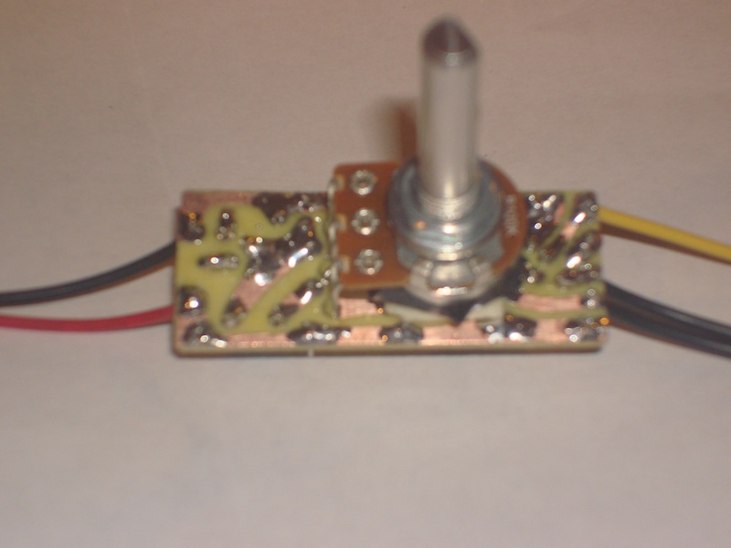
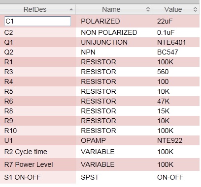
Got started with my electric brewing and yes, bought the temp controller without the manual option to adjust the boil :(, so had to come up with this circuit. I know this is out there by the zillions, just wanted to share. You simply install this between your controller and the SSR and let you adjust the power (R7) with PWM from about 10% to full power. The control cycle is adjusted by R2. The on/off switch is optional, you could modify R6 from 47K to about 39K or 27K and lower your minimum power from 10 to 0%.

SSR_PWM_2.jpg


SSR_PWM_Material.jpg
 
This may seem like a silly question - but if everything is already wired up and being controlled by your existing PID, why not simply replace the PID with one that has the manual control option?
 
Interesting, curious on SSR's, when you remove the control voltage, when does it actually open the output? Does it open immediately, or does it open at the zero crossing? Maybe I am thinking of triacs though.
 
This may seem like a silly question - but if everything is already wired up and being controlled by your existing PID, why not simply replace the PID with one that has the manual control option?

Yes, that was my first thought too, just didn't want to return the controller and wait for a new one. Also, I like the dial to adjust the power, very intuitive.
 
Interesting, curious on SSR's, when you remove the control voltage, when does it actually open the output? Does it open immediately, or does it open at the zero crossing? Maybe I am thinking of triacs though.

most common SSRs are zero crossing. if they are non-zero crossing it will normally specify that somewhere. non-zero crossing puts extra wear and tear on the device, so they are normally built a little better and are accordingly a little more expensive.
 
Oh ok thanks, will it work to try to PWM a zero crossing SSR then? It seems like the PWM signal would make the SSR close at almost random points during the line frequency wave, but then not open until the zero crossing, resulting in a lower but unpredictable average power to the heating element?
 
Oh ok thanks, will it work to try to PWM a zero crossing SSR then? It seems like the PWM signal would make the SSR close at almost random points during the line frequency wave, but then not open until the zero crossing, resulting in a lower but unpredictable average power to the heating element?

If the PWM circuit command the SSR to connect at little after a zero crossing of the 60Hz wave (worst scenario), it will hold till the coming zero crossing to actually activate the load. That is 1/120s=8.33ms. If the duty cycle of the PWM is high, like 2s, the lost power represents only 0.007%. So for a 5500W element, you get max of 5499.6W. Hope my math is correct:tank:
Note.: My understanding is that the zero crossing feature is intented to improve the device's life for inductive loads only, to avoid damage caused by a flyback pulse. For purelly resistive loads, it would not add any benefits.
 
Right, I don't think the zero crossing shutoff benefits resistive loads. I don't think there is much if any power wasted. It just seems like the PWM signal will trigger the SSR at a random point in the line AC waveform, and then even if the PWM signal opens during that half cycle the SSR won't actually open until the zero crossing. Maybe I'm just not understanding how the circuit works. Roughly what would be the frequency of the PWM signal there?
 
It just seems like the PWM signal will trigger the SSR at a random point in the line AC waveform, and then even if the PWM signal opens during that half cycle the SSR won't actually open until the zero crossing. Maybe I'm just not understanding how the circuit works.

no, that is correct. you are just thinking too hard about how much it matters that the AC waveform and the PWM pulse are not synchronized. it dosent matter that much. the AC signal will cross zero 120 times per second, so the SSR will be alowed to turn off at any of 120 points over the course of a second. even if the PWM OFF signal was triggered half way thru one wave, its only going to add an additional four-1000ths of a second to the SSR ON time, until it hits zero and turns off.

it only starts to make an actual difference if you are driving the SSR at hundreds of hertz (which you shouldnt be doing, anyway). you ideally want the PWM signal running at only a few hz, and just vary the durration accordingly. in other words- to get 75% PWM, turn the SSR on for 750ms, and off for 250 (1hz). or on for 375ms / off for 125ms (2hz). you should not be switching it like 7.5ms on / 2.5ms off (100hz), for example.

if you are doing 750ms on / 250ms off, then you can see that zero-crossing wont make any noticable difference (754ms / 246ms, or 748 / 252- is close enough to 75%)
 
Ah ok thanks, I figured if the PWM frequency were fairly low it might work, I was thinking if it was like 10kHz or something it seems like it would just always trigger the SSR shortly after the zero crossing no matter the duty cycle and it would be on almost all the time.
 
I was thinking if it was like 10kHz or something it seems like it would just always trigger the SSR shortly after the zero crossing no matter the duty cycle and it would be on almost all the time.

that is exactly correct, and is why non zero crossing SSRs are used when they need to be driven very fast. the problem with high frequency switching is that most of the heat generated in a MOSFET (which is the solid state switch inside a SSR), is not caused directly from current flowing (though obviously some heat is), but most heat is generated as the device transisions between on and off states. so the more often it switches between on and off, the more heat will be generated, even if the load is the same. this is one reason to keep the PWM frequency lower.
 

Latest posts

Back
Top