My two tier structure

Homebrew Talk - Beer, Wine, Mead, & Cider Brewing Discussion Forum

Help Support Homebrew Talk - Beer, Wine, Mead, & Cider Brewing Discussion Forum:

This site may earn a commission from merchant affiliate links, including eBay, Amazon, and others.

USCDiver

Well-Known Member
Joined
Feb 11, 2012
Messages
81
Reaction score
1
Location
Greensboro
I decided to make the jump to all-grain with a gusto. I've done half a dozen extract brews over the last few years, but the beer was never all that great. So after reading as much as I could stand and lending a hand in an all-grain session or two, I decided to take the plunge. My father-in-law is a welder. Since I'm getting a bunch of labor for free, I decided to spend the money on stainless. We spent last weekend building the basic two tier frame. Props to lehr on the design, I modeled this one after his.

001hri.jpg

Bottom Tier
002msw.jpg

Movin' on up
001eun.jpg

All done for now.

Ready for casters, heat shields and burners to be mounted next time. The burner areas are all three 17"x17" inside measurements. I'm planning to do BG-14s in all three. There is an Agri-supply nearby so I can probably avoid shipping charges and get a bargain.
 
Looking good!
Wish I knew how to weld stainless and had a nice bandsaw like you.
 
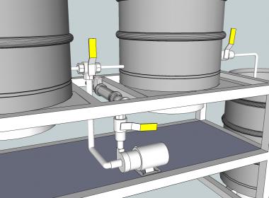
Here's my plan for plumbing the RIMS part of my build.

I'm using the Triclover 3 way valve from BrewersHardware.com as the center of this design (I haven't drawn in the the return line from RIMS tube to MLT, but it should be obvious where it goes). The tubing from each keggle will be 1/2" and the tubing from the valve to the pump will be 1". There is a regular ball valve set between the pump and the RIMS for managing flow on the back side.

I like this design for a few reasons. I can partly fill my MLT from HLT from the bottom up before pouring in my grain. Then I can begin circulating water from HLT for doughing in before transitioning to RIMS from the MLT side. This also allows me to add water from HLT into the circulation during the mash if I get stuck. Finally at the end, I can go back to HLT for sparging. Everything is also neatly contained in one small area of my structure and I don't have plumbing lines running back and forth.

USCDiverBrewStructure1.jpg


USCDiverBrewStructure2.jpg
 
I'm gonna have a 3piece valve, chugger pump, plate chiller. Just haven't put it in the diagram. Working on the RIMS part now
 
USCDiver said:
I'm gonna have a 3piece valve, chugger pump, plate chiller. Just haven't put it in the diagram. Working on the RIMS part now

Why not lower the pump you have now?
 
It would be more tubing and lower head pressures to mount it down there. My gas manifold and lines will be mounted under the shelf so it will already be in place there anyway.
 
One other thing to keep in mind, those valves close to the burners might get pretty hot depending on how close the handle gets.
 
One other thing to keep in mind, those valves close to the burners might get pretty hot depending on how close the handle gets.

There will be some sheet metal heat shields between the burners and the RIMS section. See lehr's other, single tier build for an idea of what I'm planning to do.
 
USCDiver if you are using pots you will have to make vents in the back of your heat sheilds for the hot air to escape, if your using kegs the skirts on the kegs will act as a vent.

Pat
 
Got a bit more work done this week end. We moved the MLT burner down, eliminating the space between it and the BK to make room for the three-way valve design seen above.

001peu.jpg


Here is the gas manifold we fabricated out of a piece of left over stainless tubing. More on that in a minute.

002xox.jpg


Work done for the weekend. Got the heat/wind shields installed, burners are ready to go in next.
003pgp.jpg
 
So a few words about the manifold we made. I bought three of these regulators intending to use just the regulator to control each burner instead of using ball valves. Or plan was to use copper tubing for our gas plumbing but after we dismantled the hose, we discovered that the output from the regulator is a hose barb. So we went to the local propane store and got the three regulators you can see in the pic. They have female NPT threads on both input and output. We pressure tested the manifold with about 100 PSI of compressed air prior to attaching the regulators. After attaching the regulators we rechecked the manifold with only 20PSI air. Unfortunately the regulators still put out air even when dialed all the way down to zero. So I guess we will either have to add a ball valve on each line (for off/on only, controlling the flame with the regulator) or we will try the regulators with the hose barbs and abandon the copper plumbing idea.

So I guess that brings up a question. Does a propane regulator like that require some back pressure, like from a small orifice, to work properly?
 
Looking good ! I don't think you can stop flow with that type of regulator if you think about it your gas grill not only has a shutoff valve at the tank it also has one on the grill itself.

Pat
 
Well, these regulators say they go from 0-10PSI. To me, zero means no flow, but maybe I'm wrong about that. Either way, a ball valve will fix that issue.
 
Got more work done this past weekend. We're close to having a functional system. Just got to do all the hard plumbing.

Here's my RIMS tube. I have ferrules with threaded fittings for heating element and RTD to go on either end. By the way, derrin over at BrewersHardware.com is selling those tubes with ferrules already welded to the ends. Different sizes and lengths and not very expensive. We just added the input and output ferrules.

003ofo.jpg


Here is everything we got done. Ferrules for plumbing and thermometers are welded onto the kegs. On the left in the middle you can see where we mounted the gas manifold and regulators below the shelf.

001nvo.jpg


And the burner test. Ran all three at full blast for several minutes without any troubles.
001vowa.jpg
 
Thats looking real nice! Love the last pic with the burners going full blast! Looks like it's ready for business
 
We made a bunch of progress this weekend, unfortunately I'm not going to have another free weekend until at least July! So it might be a while before I post completed pictures. Here's the latest though. Finished all of the plumbing for the RIMS system. The keggles are done except for site glasses and I need to get thermometers to go in the front of the kegs. We are adding a copper water line for the counterflow chiller and for filling the HLT. And we have to plumb the BK to chiller pump. Wiring the whole thing will be the last big step, then it's just cleaning and brewing!

001qjx.jpg


Close up of the RIMS system.

002tgq.jpg
 
Yeah, I hear ya on that. We were testing for leaks and let the pump run for 30 minutes or so outside the shop and the direct sun on the black casing and on the stainless got that thing pretty hot. I have drip/heat shields to put over the motor body and I hope that most of the heat from the burner will be going up instead of down. If it overheats, I don't know what I'll do. It is in the only feasible position for our plumbing scheme.
 
It's been a while since I had a chance to update this thread. I haven't had a weekend off in a while but by FIL has done a little extra work. We added a water line in copper that's on the back of the rig. There is an inline filter and two valves so I can use the same line to fill my HLT and then to my plate chiller. I've got everything watertight and working. I've got to get the RIMS and pumps wired (see the control arm) and then I'm ready to go.

imagehaiu.jpg
 
I have a question if anyone is still looking at this thread. Does it matter if your valve is before or after the plate chiller? I figure as long as it is after your pump it functions to limit the flow rate the same either way.
 
I think you would want it after to make sure the chiller plate is full contact with the wort, to me it seems if you restrict it before it might not fill completely.
img1881d.jpg
 
That's a good point. As I have it now I should be good. My current set-up is BK-Pump-Chiller-Valve-Fermenter.
 
So I did my first brew on this rig about 2 weeks ago. I decided to do a 10gal batch of a simple blond ale (23lbs Pale 2-row, 1lb crystal, 2oz Willamette). I ran into a few snags but otherwise a pretty successful brew day and it seems I have beer in the fermenter.

First off I couldn't get my PID to recognize the RTD probe from my RIMS tube (turns out there was a loose wire that needed to be re-soldered), so I decided to just direct fire my MLT while circulating during the mash. The dough-in went fine, but I think my thermometer probe on the MLT is off by 7-10 degrees (and I couldn't get to that damn adjustment screw while it was clamped on). Halfway through the mash, my RIMS pump overheated and shut down. At the time I chalked it up to the MLT burner throwing some heat down that way which shouldn't be a problem once my RIMS tube is working correctly. Anyway, we just shut off the gas and let the pump cool down. Temps were fairly consistent, but with the thermometer inaccuracies, I don't have a clue how close I was to my target.

Either way, we made it to sparge with no other problems. I foolishly turned off the burner on my HLT when I hit sparge temp and it lost about 15* during the sparge. Lesson learned there. I'm pumping my sparge water through the RIMS tube, so I suppose I could use the heating element to help maintain that temp as well. Unfortunately the dang pump overheated again during sparge, despite the MLT burner being off. The only thing I could figure was that the splash guard was not allowing enough air to circulate around the pump fan, so I took it off and put a ziplock full of ice over the pump housing. It cooled off quickly and we proceeded to sparge. I vastly under estimated my losses due to grain absorption, so I had to heat up another few gallons to reach my target (12 gallons).

Despite all those hiccups I managed to hit my pre-boil gravity pretty close to goal. I think I was about 70% on my mash efficiency. I'll be more careful with my measurements once I get this thing running more smoothly so I can get a better idea of what my efficiencies are.

Boil, chilling and pitching all went off without a hitch.

There was only one other issue: I used a 'contractor grade' 6.5hp wet-vac I picked up from Lowes to suck my spent grain out of my MLT and the damn hose collapsed. I don't know if it was a combination of the heat and the thickness or what. I'm going to take the thing back and get another one (still under warrenty).

After I got the RTD and PID working correctly a few days later, I ran the RIMS tube/pump for about an hour at 140* without any trouble from the pump. So I think I'll leave the splash guard off during brew days and only put it back on during cleaning to prevent any major spills. There are additional splash guards on the top tier which should catch any small spills during brew days.
 
Back
Top