wyzazz
Well-Known Member
Looking very good, I can't wait to see more pics!


This is big. I'm thinking you can recuperate cost by giving tours of your basement.
Wow! Can we get a close up shot of the brazed tri-clamp. One of my biggest conundrums in the rebuild of my system is finding/building a sanitary (or as close as possible) chiller, so any help on that end would be great

") Thanks!
Thanks!Thanks, that helps. What did you use to drill out the cap since the metal is so thick? Also did you secure the tri clamp cap so that it was set on top of the npt fitting, then braze by focusing most of the flame on the nptport and just work your way around. If so how did you avoid any downward dripping? Pardon my ignorance, but I am just that when it comes to brazing


wyzazz said:If you're looking for a stainless wort chiller you can snag one from here, well built and the price isn't bad either. As an added bonus they also sell rolls of tubing.
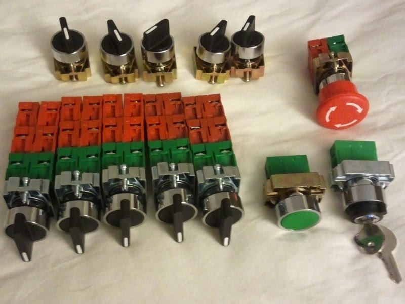
bgarino said:Where did you get your switches from?
Is this it? http://www.elecdirect.com/
great thread, and epic build! Please post, when it happens, how you did with the waterjeting, and what it cost. I'm presently getting quotes on cutting a stainless door for a control panel (much, much less elaborate than yours), and am curious how it prices out around the country. I've gotten two quotes for $190 and $290 for 13 round holes and 4 square cutouts for PIDS in the Boston area. Good luck with your continued build.


Wow what a system. I am just going to start hating you right now, if that is ok with you.
I may have missed it somewhere in this thread, but what touchscreen are you using?
The touchscreen is an older panel pulled from a Kodak photo kiosk or similar. It is made by ELO and is similar to the 1537L. 1024 x 768 Resolution, it was around $40 on eBay a year or two ago.
I thought mototrized ball valves, or at least the ones in home brew rigs, only went fully open or fully closed. Is the controller board handling some type of actuator or have you gone and bought actual control valves? Are all the valves, apart from the solenoid ones, going to have this functionality? Great work on the PCB's!!
Remind me to send you a PM when I start planning for world domination!


I look forward to receiving the custom heat exchanger coil inlet tubes you built for me!Subscribed

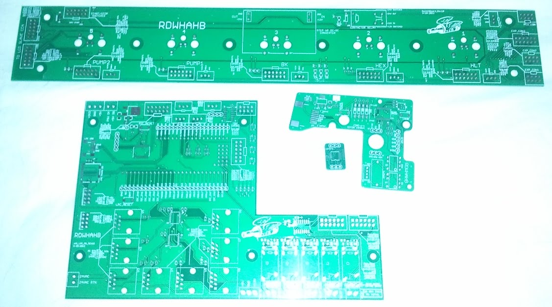


love the logos and the rdwhahb on your boards. nice touch
I look forward to receiving the custom heat exchanger coil inlet tubes you built for me!
I know this should be obvious from the thread but can i just ask are all 7 of the ball valves going to have 0-100% flow control & does that mean a stepper motor is required at each one?
I think given the fact that this project has been underway for less than a year you've achieved an awful lot in a very short time span:rockin:
Can we be friends?. I am sure we can be BEST friends!! really I promise.........
But seriously can we???
(this is blowing my mind!!!!)
jokes aside (and im sure this was mentioned before) but, what would be the cost if I where to comission a system like this?

You gonna use your peristaltic pump with this system?


Enter your email address to join:
