Thinking about going electric

Homebrew Talk - Beer, Wine, Mead, & Cider Brewing Discussion Forum

Help Support Homebrew Talk - Beer, Wine, Mead, & Cider Brewing Discussion Forum:

This site may earn a commission from merchant affiliate links, including eBay, Amazon, and others.

wbyrd01

Well-Known Member
Joined
Jul 23, 2012
Messages
145
Reaction score
19
Location
Gilbert
Like the title says, I'd like to go electric. Tired of getting propane and with summer coming I'd like to get away from the heat that propane brings with it. I do want to do this as cheap as possible though. I'm thinking of using my current 36 quart stainless pot as an HLT (refilling and reheating additional water after mash in as needed), a cooler for my MLT, and buying a keg to make a keggle. I want to use one 5500 watt heating element in the HLT and one in the keggle. I don't care to automate temp control since the cooler won't lose much heat over the course of a one hour mash. If I can use a rheostat in place of a PID temp controller then I would like to go that way, unless the rheostat is somewhat close in price to the PID controller. I don't think I would need to regulate the element in the HLT since I can just turn it off once I hit the temp I need. So I think I would only need to regulate the element in the keggle to control the boil.

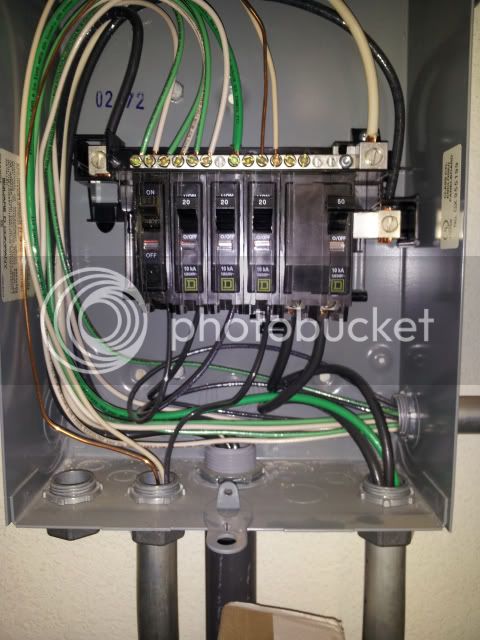
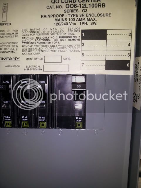
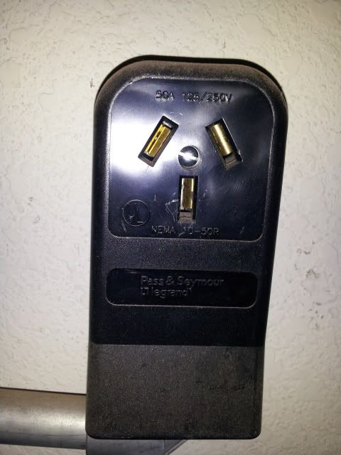
I used to build custom motorcycles and had a large TIG welder so I already have a 240v 50 watt panel in my garage. Here are pictures of what my electricity supply looks like:

1d9f02da79f6d8d9eec9907328c32958.jpg


f745ee10ffad8929b15fc5b0aa7e21a1.jpg


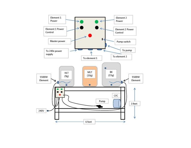
And this is a sketch I made of what I would like my setup to look like. On my sketch of the control panel I have a controller for the HLT element but I don't think I'll need it.

e7946112a71f7c447534d4d85ced94d3.jpg


My plan is to just use one pump to move liquid, changing connections as needed.


I've been looking through quite a few of the build threads but I don't think I've seen any that use a rheostat to control the power on the elements. I appreciate any input on whether or not my ideas will work and possibly a list of what components I will need.

Here are a couple of questions I've come up with so far:

Can I use a rheostat to control the power to the elements?
Does it hurt the elements to have the power received reduced?
Will I need a heat sink in my control panel?
Do I need a spa panel or is what I have already taking care of that?


Thanks all!
 
If your goal is to do this as cheaply as possible, then you could just implement this system with a single electric kettle.

Use it as your HLT to heat mash water.
Move that water to MLT and mash in.
Use it again as an HLT to heat sparge water.
When mash is done, move the hot water to some third tank for a moment, move wort to e-kettle, move the held hot water in for sparge.
Drain the remaining wort to the e-kettle.
Use it as a boil kettle now.

All you added to the process was the one transfer of water.


A rheostat that can handle a 5500W is going to cost you a small fortune, so you are going to want to go with an SSR and either a simle PWM (pulse width modulator) to control the boil strength, or a PID that supports manual mode.

I was actually thinking of doing the one electric kettle thing at first, just to get me started until I can piece together the rest.

A PID that supports manual mode would be like this correct? http://www.amazon.com/dp/B007JB6TA8/?tag=skimlinks_replacement-20

Is there a way I could add GFCI protection to what I already have without using a spa panel?
 
Last edited by a moderator:
I was actually thinking of doing the one electric kettle thing at first, just to get me started until I can piece together the rest.

A PID that supports manual mode would be like this correct? http://www.amazon.com/dp/B007JB6TA8/?tag=skimlinks_replacement-20

Is there a way I could add GFCI protection to what I already have without using a spa panel?

I don't think that PID has a manual mode. You want one in which you can specify a duty cycle, so that you can control the boil. Many people on these forums, myself included, use one from Auber Instruments (http://www.auberins.com/index.php?main_page=product_info&cPath=1&products_id=3).

The only other way to add GFI is to swap out the breaker which is probably more expensive than the spa panel.
 
Last edited by a moderator:
I was actually thinking of doing the one electric kettle thing at first, just to get me started until I can piece together the rest.

A PID that supports manual mode would be like this correct? http://www.amazon.com/dp/B007JB6TA8/?tag=skimlinks_replacement-20
Nope. That TA4 PID does not support manual mode, but the TD4 from the same manufacturer does. You can get it for a pretty good price on amazon, bundled with an 25A SSR that could handle the 5500W element:
http://www.amazon.com/dp/B0087O6RO4/?tag=skimlinks_replacement-20

I've seen it bundled with a 40A SSR for pretty much the same price, but I can't find that one with 30 second of searching, but poke around. Also, that one I linked to is Celsius, but I think they can be found for Fahrenheit, too.


Is there a way I could add GFCI protection to what I already have without using a spa panel?

Sort of. Your current service is 50A and 240V, but it doesn't have a ground. That type of outlet (if wired properly) provides hot, hot, and neutral. I think you *might* be able to swap out the breaker and put in a 50A GFCI breaker, but the fact that you have no ground is kind of ugly.

But, more importantly, I can tell you from experience that a 50A GFCI breaker for your panel (which is the same as my own) will run you well over $100 unless you get lucky and find a bargain. The Spa panel is almost always the cheaper route to go to get GFCI. $50 at home depot.
 
Last edited by a moderator:
I think you *might* be able to swap out the breaker and put in a 50A GFCI breaker, but the fact that you have no ground is kind of ugly.

I think code allows GFCI without a ground, but you are supposed to label the receptacles to say that they are ungrounded.

I have the same thing in my garage, a 50A 3 prong welder outlet, but I just put in the spa panel. It was cheaper than buying a breaker anyway.
 
Just to be clear. When you guys are talking about changing out that 3 prong with a spa panel you still have a a breaker in the main box correct. So you'd have main breaker -> spa panel w/gfci breaker -> 4prong plug?
 
In addition to the GFCI, I would install a 240v 4-wire outlet so that your panel has the Neutral for 120v pumps and the Gnd for the 240v elements.

Search for "voltage resistance SSR" for a simple analog power control for the element.

If you want to run both elements at once (using full 50amp service) then consider using 4500W for one or both elements.
 
Nope. That TA4 PID does not support manual mode, but the TD4 from the same manufacturer does. You can get it for a pretty good price on amazon, bundled with an 25A SSR that could handle the 5500W element:
http://www.amazon.com/dp/B0087O6RO4/?tag=skimlinks_replacement-20

I've seen it bundled with a 40A SSR for pretty much the same price, but I can't find that one with 30 second of searching, but poke around. Also, that one I linked to is Celsius, but I think they can be found for Fahrenheit, too.


Like this?

http://www.amazon.com/dp/B008ZUDUSG/?tag=skimlinks_replacement-20
 
Last edited by a moderator:
I think code allows GFCI without a ground, but you are supposed to label the receptacles to say that they are ungrounded.
That type of receptacle is ungrounded by definition (if wired the way it is supposed to be wired).

Just to be clear. When you guys are talking about changing out that 3 prong with a spa panel you still have a a breaker in the main box correct. So you'd have main breaker -> spa panel w/gfci breaker -> 4prong plug?
What many people do is:
Main breaker -> 3 prong outlet -> spa panel w/gfci -> 4 pring outlet.

You basically split the neutral line from the existing outlet into two versions. One that you use as neutral and is allowed to carry current, and one that you use as a ground that is not allowed to carry current.
 
That appears to be right. But it's weird that the title of the listing ends in a question mark. :D

Yeah I thought that too. It's like they're not quite sure if it's C or F.


Ok, so starting with just one electric kettle with no pump it looks like I'll need:

Spa panel w/gfci
4-wire 240v outlet
5500 element
Control panel (will probably use a tool box)
TD4-SNR
Junction box for the element.

What am I missing?
Do I need a heat sink?
Do I need any switches? Probably at least one for master power?
What size wire should I use?
What receptacles do I need on the control panel to hook power up to it and to run power out of it?


I really appreciate the help!
 
Another small detail to consider is that you will get stratification in your HLT so will need to mix it to get a real temp reading. Many, including myself, use a pump to recirculate the hot water while bringing it up to temp......
 
Yeah I thought that too. It's like they're not quite sure if it's C or F.


Ok, so starting with just one electric kettle with no pump it looks like I'll need:

Spa panel w/gfci
4-wire 240v outlet
5500 element
Control panel (will probably use a tool box)
TD4-SNR
Junction box for the element.

What am I missing?
Do I need a heat sink?
Do I need any switches? Probably at least one for master power?
What size wire should I use?
What receptacles do I need on the control panel to hook power up to it and to run power out of it?


I really appreciate the help!

RLTW,

I can't answer most of your questions, but I will let the pros chime in, just wanted to wish you best of luck. I just finished my system and will be brewing on it tomorrow for the first time tomorrow. I would ask PJ for help on wiring diagram and needed gauge of wires, I used 6-12 in mine good luck
 
Really informative article on electric kettle it was! I impressed from the presentation and process of "sketch of the control panel" but spa panel will be fine for you.
 
Here you go - it's OK to use GFCI with ungrounded receptacles, but they should be labelled "No Equipment Ground".

http://www.nachi.org/ungrounded-electrical-receptacles.htm

You defiantly don't want to run a brewery without an equipment ground, that would be worse then running with no GFCI IMHO (I doubt that's what you were suggesting).

EDIT: My mistake, I didn't look at the picture of the plug... it is ungrounded. Best bet is already as suggested above, tieing the ground to neutral at the spa panel/GFCI.
 
You defiantly don't want to run a brewery without an equipment ground, that would be worse then running with no GFCI IMHO (I doubt that's what you were suggesting).

His welder plug should have a ground, just no neutral (again, you defiantly want an equipment ground for a welder).

I believe I can split that ground in to two so I'll have a ground and a neutral for running 120v components as well. Is that correct?

And is there a way I can test my welder plug to make sure my third wire is a ground?

Doh! You edited your post while I was editing mine! I think I understand what I need to do. Lots more research!
 
And is there a way I can test my welder plug to make sure my third wire is a ground?

You can look at how/where it's wired. But both ground and neutral should be connected together in your panel, so you can't measure it.
 
Ok, here's what the inside of my panel looks like. I'm thinking my welder plug is wired for no ground. It looks like the two big black wires are my two 120 legs and the green wire is going to the neutral line where all of my 120v lines are going. Correct?


1926a315dfae33884736bb933dc8af66.jpg
 
Yea, your grounds and neutral bars should be separate, yours are tied together. I would call your wire to your welder a ground solely because they ran green wire. As both your neutral and ground are bonded at the sub-panel its a bit of a moot point.

In modern code this is a no-no, you should have a 4 wire feed to your sub-panel, and the neutrals and grounds kept separate (will be tied at main panel). However I'm not positive (my history isnt that good) but this only became mandated in the NEC sometime in 2005-2008. Its also a very common violation as it saves people $$$ by not running the extra conductor to their sub-panel.

As you appear to have conduit, you could pull an extra neutral wire from your welder plug to your sub-panel, but as they are bonded there anyway I'm not sure its worth the effort.... I doubt you want to get in to re-wiring the feed to your subpanel either.

It's going to come down to how far you want to take it.
 
Back
Top