Wiring schematic for switchable 110v/220v control panel critique needed

Homebrew Talk - Beer, Wine, Mead, & Cider Brewing Discussion Forum

Help Support Homebrew Talk - Beer, Wine, Mead, & Cider Brewing Discussion Forum:

This site may earn a commission from merchant affiliate links, including eBay, Amazon, and others.

WPStrassburg

Well-Known Member
Joined
Sep 30, 2008
Messages
598
Reaction score
48
Location
Rochester, NY
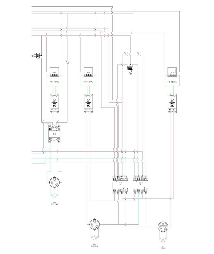
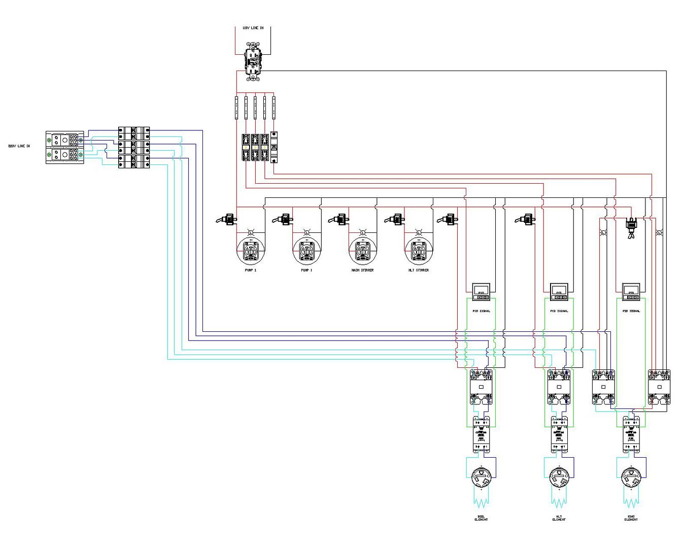
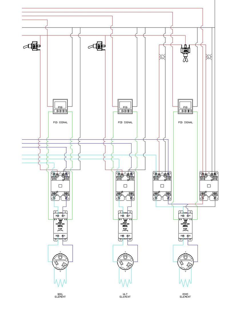
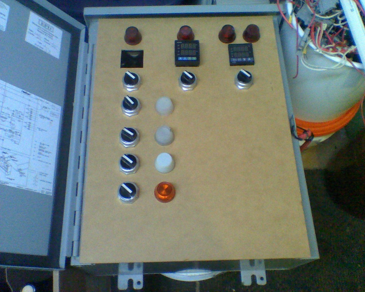
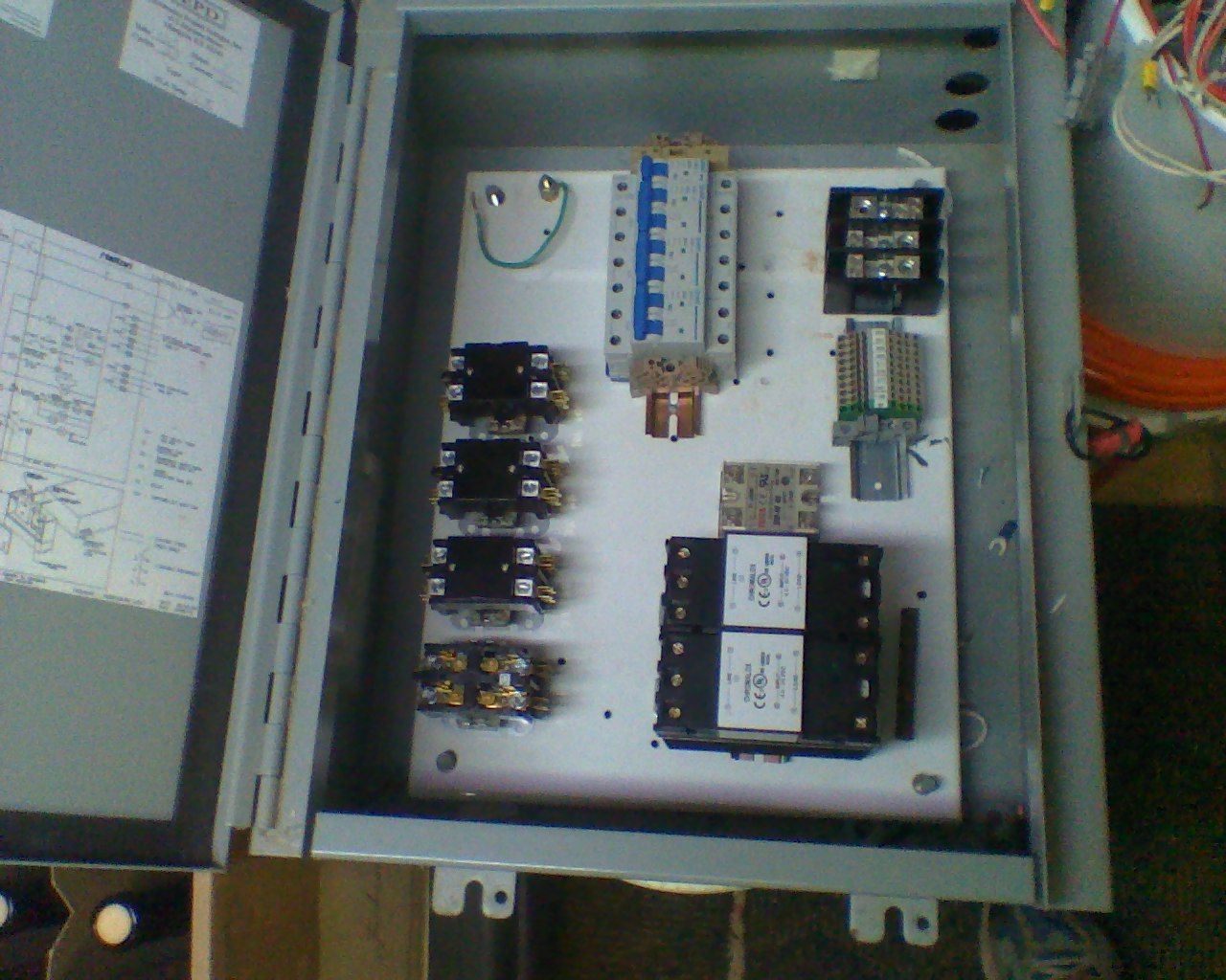
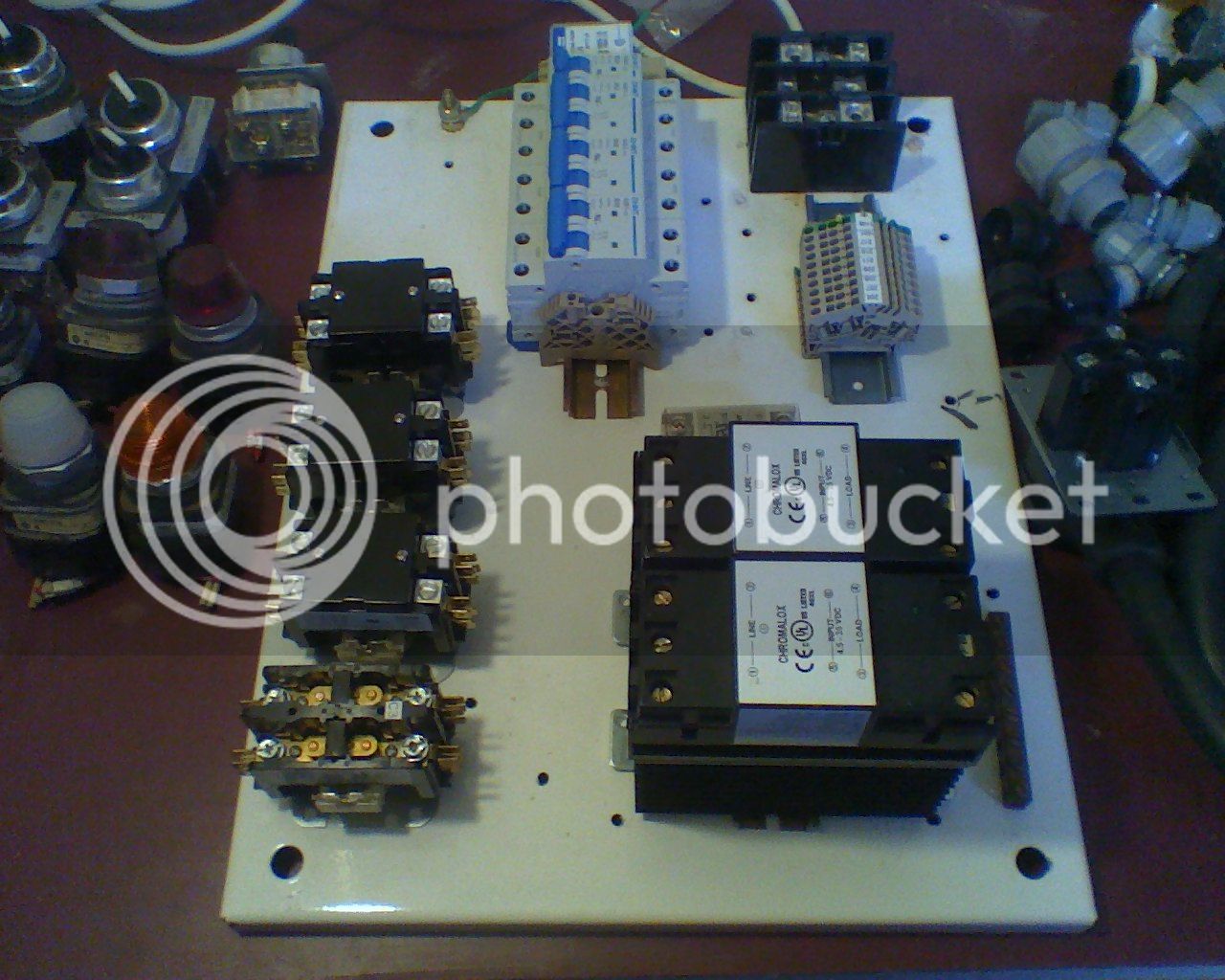
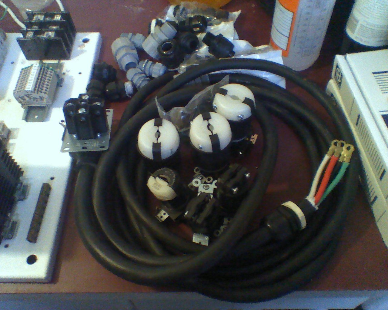
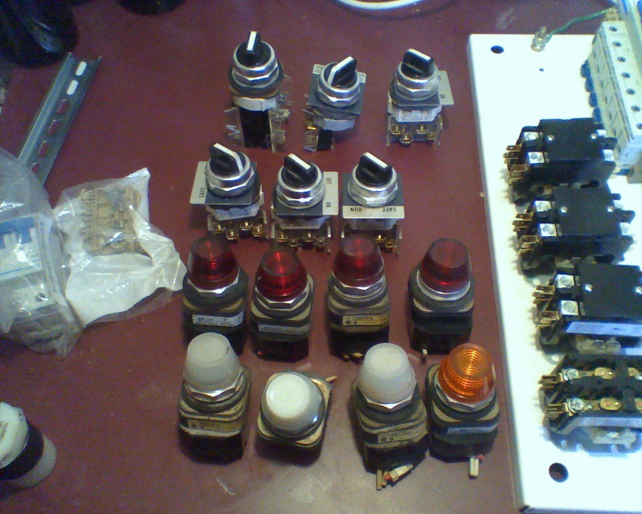
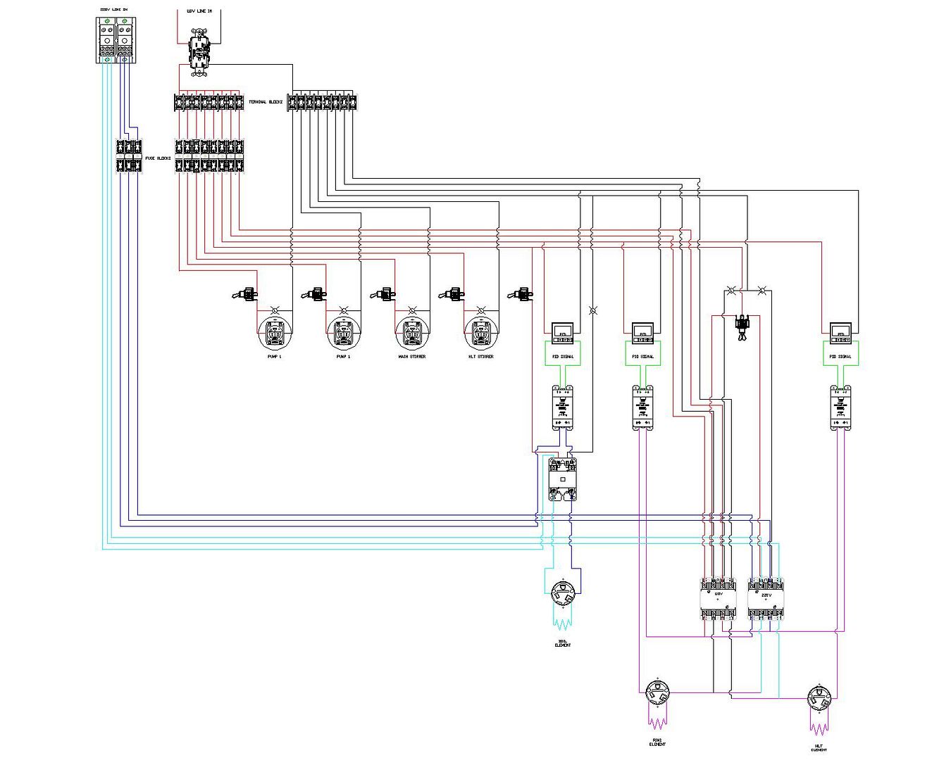
I've been working on getting a schematic together for my control panel and think I'm getting pretty close, but I'd like some commentary. I'm doing a basic manual control for my system to switch 2 pumps, 2 gearmotor stirrers for the hlt and mash tun, a 220v 5-6kw boil element, a rims element, and a hlt element. For the rims and hlt I'd like to be able to switch the power between 110v and 220v so I can brew on 220v in the basement during the winter and then outside on NG with 110v rims and hlt control. The thought is that if I can switch between 110/220 I can control the elements with 2 pid's instead of 4. I currently have two 4 pole contactors to switch between 110 and 220 via a 3-way, center off, switch. All the 110 power will be through a gfci receptacle and the 220 will be through a 50A gfi breaker. I'm trying to stay flexible, but not complicate the panel too much. Thoughts and comments please.
Thanks,
Walter

WiringSchematic-2.jpg
 
I'm actually planning on moving my 220v rims element to switchable 110/220. I'm on my 5th brew on the system and the rims element gets a strong build up of gunk caked on. I'm on an HLT-less system and while I need 5,500 220 to sparge 70f tap water I should be able to re-circulate using 110v. Not sure this helps you, but I'm looking forward to this flexibility in the future.
 
The thought is that if I can switch between 110/220 I can control the elements with 2 pid's instead of 4.

You lost me there. What does the 110/220 selection have to do with the number of PIDs?

You mentioned "2 PIDs instead of 4", but the diagram has 3 PIDs, so I am not understanding things here.

I don't think you'll be able to support two stir motors, two pumps, the RIMS element, and the HLT element on a single 120v circuit for those days when you are brewing outside.


I am a little lost trying to follow the wiring around those 4-pole contactors, too. I can't tell what is coil control and what is load wiring.
 
You lost me there. What does the 110/220 selection have to do with the number of PIDs?How do I change between 110 and 220 going to the elements without adding another pair of pid's?

You mentioned "2 PIDs instead of 4", but the diagram has 3 PIDs, so I am not understanding things here.
3 pid's total. one would be the boil pid and that would be 220 only. the other two will be hlt and rims. I'm looking to switch the hlt and rims between 110 and 220. Is there another way to control a single element via a single pid with either 110 or 220?

I don't think you'll be able to support two stir motors, two pumps, the RIMS element, and the HLT element on a single 120v circuit for those days when you are brewing outside. I was figuring on a 2kw 220v hlt element, and a 4kw rims element would be 1.5kw on 110, but dual 20A circuits to feed the elements and pumps are an option too. I'd just add another gfi outlet and split the elements, pumps, and gearmotors between the two circuits.


I am a little lost trying to follow the wiring around those 4-pole contactors, too. I can't tell what is coil control and what is load wiring.

Here's a little better view of the contactors and I've attached the jpeg of the schematic.


WiringSchematicPID.jpg


Wiring Schematic.jpg
 
Here's a little better view of the contactors and I've attached the jpeg of the schematic.

OK. I understand that part now. Still not clear on the comment about 2 pids vs 4 pids and the diagram that uses 3 pids.

And I'll repeat that a single 120V feed into the box will not be able to support your stir motors, pumps, PIDs, and 2 heater elements on those days when you want to brew with 120V.

I think some of your lights are shown as being in series with other electronics when they should be in parallel with them.

edit: IMO, the stirrers are not even necessary.... at least the one in the MLT.

For the pid's it is 3 vs 5 if I look at the total. And now that i think of it it will be only 3 pid's, but how many scr's is the real question, 3 or 5? (electrical revelation #1 of the day...) One pid/scr for the boil element at 220, then the hlt will need 1 pid and at least 1 scr, and the rims will need 1 pid and at least one scr. Can I use the 1 hlt scr with both 110v and 220v if I switch the voltage with the contactor(and another rims scr with both 110v and 220v)? Or will I need 1 hlt 110v scr, 1 hlt 220v scr, 1 rims 110v scr, and 1 rims 220v scr?

Totaling up the loads you're right about when I'm outside, so I'll pull the hlt from a second 110v circuit and run the pumps and rims off the main 110v for the days. I may not even screw with the hlt on the 110 since I can direct fire the hlt if I'm outside to get it close and then once I'm sparging flop the element plugs and sensor and use the rims pid to maintain the hlt. Or just circ the hlt water through the rims tube when I'm sparging to get 170* sparge water.

Got the lights fixed to parallel wired for the 3 contactors.

The stir motors are an option and day one I'll just have 2 switched receptacles that may or may not control gearmotors. I could just as easily run a pump to circ the water in the hlt if I get any temp variances.
 
One pid/scr for the boil element at 220, then the hlt will need 1 pid and at least 1 scr, and the rims will need 1 pid and at least one scr. Can I use the 1 hlt scr with both 110v and 220v if I switch the voltage with the contactor(and another rims scr with both 110v and 220v)? Or will I need 1 hlt 110v scr, 1 hlt 220v scr, 1 rims 110v scr, and 1 rims 220v scr?
You only need 3 SSRs for functionality, drawn exactly like you have it.
 
I just noticed today that I only have one of the 2 220v hot lines fused and no neutral shown. That got me thinking about where the neutral would actually go besides into the control panel and stop at the distribution block? I'm not splitting the legs and using 110v from the 220v feed, so I'll have nothing coming off the neutral block in the control panel besides the wire from the main breaker panel coming into it, right? I'm also going to redo the the scr/contactor wiring so both legs go through the contactor first then one go to the scr then element and the other to the element. That way if the switches aren't on I will have no power past the contactor and no power on the scr or element.
 
I just noticed today that I only have one of the 2 220v hot lines fused

I noticed that, but was going to ask you what your source even was. 30A? 50A? More?


and no neutral shown. That got me thinking about where the neutral would actually go besides into the control panel and stop at the distribution block? I'm not splitting the legs and using 110v from the 220v feed, so I'll have nothing coming off the neutral block in the control panel besides the wire from the main breaker panel coming into it, right?

Right. You don't need the neutral from your 220V source. You don't even need to bring it into the box at all if you don't want to.

I'm also going to redo the the scr/contactor wiring so both legs go through the contactor first then one go to the scr then element and the other to the element. That way if the switches aren't on I will have no power past the contactor and no power on the scr or element.

Either way is fine and there is no right or wrong way to do it.
 
oh. nevermind. I see in the 1st post that it's 50A. You will need to put fuses or breakers on those lines for sure.
 
I noticed that, but was going to ask you what your source even was. 30A? 50A? More?


Right. You don't need the neutral from your 220V source. You don't even need to bring it into the box at all if you don't want to.


Either way is fine and there is no right or wrong way to do it.

50A breaker in the panel to a 50A spa panel in the brew room. Everything will be fused after the distribution blocks. I plan on fusing based on the equipment connected(eg .5A control fuse, 2A pump fuse, 2A gearmotor fuse, and 20, 25, & 30A element fuses), but wiring with 12ga for the 110v and 10ga for the 220v as all my wiring devices are 20A 110v and 30A 220V. Sound right?

I've got the wire already so I'll have the neutral to the spa panel and a 4 wire range cord.
 
WiringSchematicrev2.jpg


WiringSchematicPIDrev2.jpg


Simplified my wiring and removed the fusing for the pumps and stir motors as I'll be using a 20A feeed for those. I may still pull the 110v rims from a separate circuit if I have problems. I kept the 110V 20A breaker just for additional piece of mind to act as a disconnect while I'm on 220V power. The 4 pole contactor were too much of a pain and I figured I'd only be using the rims if I was outside brewing on gas so I ditched the 110v HLT as well.
 
can you post some updates of the final system and wiring schematics? I hope to build something like this soon
 
Backboard is wired up and that's about it.....

Hopefully will pick it back up this winter and finish it up. Ended up adding a fourth SSR and powering it independently from 120v so I didn't have to worry about flipping voltage sources with a contactor for the RIMS. I can post up a revised schematic in a few days when I get back in town.
 
Back
Top