DIY glycol chilled plastic conical fermenters

Homebrew Talk - Beer, Wine, Mead, & Cider Brewing Discussion Forum

Help Support Homebrew Talk - Beer, Wine, Mead, & Cider Brewing Discussion Forum:

This site may earn a commission from merchant affiliate links, including eBay, Amazon, and others.
I am wiring up now. The driver board connections don't seem to accept the 14ga wiring. What is acceptable ga? I have some 20-22ga speaker wire. Seems 18ga may even be too big.

What's this board do? Amplify the output signal to the ball valves??


Thanks.

TD
 
FYI-

that Frigidaire unit Packet used is getting scarce....

TD

EDIT

Also, Packet is right, soldering wire onto the XLR connectors is a PITA. I got the panel mount parts soldered up. I can't imagine trying to do it with a pencil style soldering iron. I used an ancient 340Watt Weller Soldering Gun!

In the Plastic conical site, for the XLR connectors on the Ball Valve outputs. These go through the Driver board. The driver board is grounded to chassis. There is no indication of the XLR connectors getting the ground hooked to anything. Is that right? The other set of XLR connectors for the temp probes get grounded back to the BCS (pin 2).
Does pin 3 ground internally into the connector itself (the metal housing part) or is it isolated as well ? just curious without getting out the ohm meter...

I think my wiring is all done for now until I can get the enclosure back and start mounting the guts inside.

TD
 
I am wiring up now. The driver board connections don't seem to accept the 14ga wiring. What is acceptable ga? I have some 20-22ga speaker wire. Seems 18ga may even be too big.

What's this board do? Amplify the output signal to the ball valves??


Thanks.

TD

20-22 gauge is what I used.

The reason for the board is that the BCS can't really drive much in the way of power, even when it comes to relays. The BCS is supposed to put out 5V, but when you hook everything up, it usually puts out ~3.3V. The ball valves usually require 9-12V (depending on the model you get). So, the board just steps up the voltage from whatever the BCS puts out to the 12V that the ball valves need.

My only word of caution is to leave at least one empty terminal between connections on that board. I had a lot of issues with crosstalk between the channels until I moved them around a bit.
 
FYI-

that Frigidaire unit Packet used is getting scarce....

TD

EDIT

Also, Packet is right, soldering wire onto the XLR connectors is a PITA. I got the panel mount parts soldered up. I can't imagine trying to do it with a pencil style soldering iron. I used an ancient 340Watt Weller Soldering Gun!

In the Plastic conical site, for the XLR connectors on the Ball Valve outputs. These go through the Driver board. The driver board is grounded to chassis. There is no indication of the XLR connectors getting the ground hooked to anything. Is that right? The other set of XLR connectors for the temp probes get grounded back to the BCS (pin 2).
Does pin 3 ground internally into the connector itself (the metal housing part) or is it isolated as well ? just curious without getting out the ohm meter...

I think my wiring is all done for now until I can get the enclosure back and start mounting the guts inside.

TD

Ground the driver board to the ground on your BCS. Otherwise you may have a floating ground. If I didn't note that on the wiring diagrams, I'll have to change it.

The temp probes just use a resistor and it doesn't matter which side is positive or ground since it works both ways.

The ball valves just connect to the negative bus to complete the circuit. If you look at the wiring on the ball valve, it's only two wires.

As for the A/C unit, they'll probably have more this summer. You really just need the cheapest analog unit you can find, and then follow the wiring diagram on the inside to hard wire it to be on high A/C every time the unit is powered on.
 
For the chassis ground, use one of the ground connections on the chassis (they're threaded studs). Just crimp a ring connector on the end of a wire and put it over the stud. Use a nut to tighten it down when you're done. Be sure only to run the 110v ground through those though. The 5v ground goes through the BCS. The 12v ground goes through the 12v power supply.

Packet,

So on the "blog" site, your pictogram of the driver board wiring has the driver board ground connected to chassis ground.

I understand a little bit about ground loops and the importance of not having more than one ground point. I know it can cause noise in car audio circuits. Other than that, I know nothing about it beside it being poor practice for electronics wiring. For lighting, or regular electrical It might be OK. With respect to this project however, and in light of your previous post about the driver board being grounded through the BCS....

For the chassis ground, I will ground the internal outlets, the external outlets, the DC PSU, and that's it.

For the BCS "ground". Well, the unit itself does not appear to be grounded to the chassis at all. Its power is from its own wall-brick PSU plugged into an internal 120vac outlet. It has three terminals labelled "GND". Running from left to right across the back, the first GND is connected to the SSRs. The second GND is not connected to anything. the last GND is connected to the temp probe XLR pins.

The third pins on all XLR connectors are not grounded to or connected to anything.

The Driver board Ground is connected to the chassis ground right now, per your pictogram at plasticconical. In your last post, you say its to be connected to the BCS GND. Do you know which of the three it gets connected to?

I'm going to have to track down the manual on the BCS at some point. I see also it has +5VDC terminal. I am wondering if one of the GND connections is really the -12VDC for this voltage supply(?)


ASIDE for any using 7 segment displays (AKA PID Display Module)
I am also planning to connect 7-seg LED displays for the three tanks. There is a temp gauge on the glycol reservoir so a digital display is of no benefit. For any interested, there is a thread here somewhere that details easily how the connections to the BCS are made.
The thread discusses a ground running to the BCS, but again, there is no mention of which GND terminal used, and the connections in the single picture show the ground running below the BCS perhaps to a chassis ground along with another wire from behind the panel plate. Also, the terminal block for the ground wire as pictured in the thread on the PID Display is not present on my PID D.M.'s. Fun times... Looks like I'll be writing an email to OSCSYS.COM

wish I knew how to multi quote from multiple threads and posts...

TD

The BCS uses negative as a ground. It's not a true ground, but the driver board appears to be rather sensitive. So, it's easier to use the BCS as ground.
 
I was able to determine over on the ECC forum that the BCS GND terminals are all common and they have three because of so many connections to GNS being required. So it really doesn't matter which you use. The PSU you linked to in your blog/plasticconical site has an adjustment knob, so I'm wondering if it could be tweaked so that the -VDC matches the BCS, though I sort of wonder if this really matters. I saw a couple folks running the BCS, and other DC components off the same PSU with step down components, probably a resistor array, for each component. This may be an option if I run into problems, but I doubt that will be necessary.
It was recommended also that I ground all DC and AC (Ground, not neutral) to common ground.

It also seems that I'm probably not going to be able to hardwire to my network because there is no way to change the IP address of the BCS that I am aware of. A WiFi adapter would do this however it seems. We'll see, I haven't heard back on that yet. I did find out there is a iPhone app called brew buddy that will let you access your BCS from your phone, though probably you can already do this via the safari browser if you're on the same WiFi netowrk. May be worthwhile to check it out though.

Anyway, I think I get my stand and painted (hopefully) enclosure back very very soon. Maybe this weekend. Finding time to assemble the conical will take a while. Which reminds me, the I missed the sale at Agrimart on the two additional conicals I want! Still needed is a cooler and the neoprene wrap. AC unit ordered and will be here before end of week.

TD
 
I was able to determine over on the ECC forum that the BCS GND terminals are all common and they have three because of so many connections to GNS being required. So it really doesn't matter which you use. The PSU you linked to in your blog/plasticconical site has an adjustment knob, so I'm wondering if it could be tweaked so that the -VDC matches the BCS, though I sort of wonder if this really matters. I saw a couple folks running the BCS, and other DC components off the same PSU with step down components, probably a resistor array, for each component. This may be an option if I run into problems, but I doubt that will be necessary.
It was recommended also that I ground all DC and AC (Ground, not neutral) to common ground.

The 12V power supply needs to stay at 12V as it runs the ball valves, which need 9-12V. It doesn't supply any power to the BCS.

It also seems that I'm probably not going to be able to hardwire to my network because there is no way to change the IP address of the BCS that I am aware of. A WiFi adapter would do this however it seems. We'll see, I haven't heard back on that yet. I did find out there is a iPhone app called brew buddy that will let you access your BCS from your phone, though probably you can already do this via the safari browser if you're on the same WiFi netowrk. May be worthwhile to check it out though.

You can set the BCS to either use DHCP and pull an IP from your router, or to set a static IP. I'd probably set a static IP as you then know what IP to use for the BCS. All you need to set it up is a crossover cable attached to your laptop/desktop. Set the IP and hook it up to your network. Then you're good to go.
 
Good to know on the IP stuff

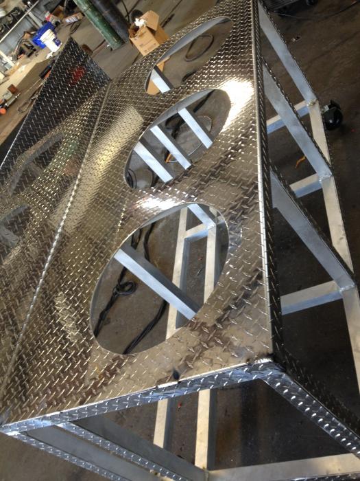
Visiting the welder today. Here is a sneak peek. ImageUploadedByHome Brew1390577123.140591.jpg
TD
 
Cart and control panel enclosure will be home on Monday for me to start putting it all together. The control panel enclosure will stick out a bit off to one side, mounted below the deck. In hindsight, I should've had a post standing straight up in the back middle and mounted to that. It should be just fine where I'm gonna put it. I didn't want to put it at the back, because would be difficult to get to in case I needed, and might cause issues with placement of the glycol chiller / cooler. That reminds me... I need to buy a cooler still (And the neoprene). Haven't figured out how to mount the PEX tubing to the metal yet. I will probably use zip ties and the square sticky things to rough it in, then I may use expoy cement or else rivets (yuck) to connect the plastic mounts that Packet used ( though I worry trying to rivet them they might break ) I may end up mounting to the rear side of the back-splash. Haven't figured that part out. I might involve some cutting/drilling. No word yet on what this cart is going to cost me aside from the casters and caster hardware. The diamond plate really looks nice in person.

TD

IMG_1173.jpg
 
That is quite the cart you've built there. I think I spent 3 hours on mine total, and more than half of that was finishing the wood top.
 
Question for Packet.

On the neoprene. They sell a regular and a high quality version. Which did you use? Seems the density of the HQ stuff is higher. Have you had any problems with the insulation coming off? What kind/brand of tape did you use to attach?

Thanks...

TD
 
Question for Packet.

On the neoprene. They sell a regular and a high quality version. Which did you use? Seems the density of the HQ stuff is higher. Have you had any problems with the insulation coming off? What kind/brand of tape did you use to attach?

Thanks...

TD

I bought the regular neoprene. Haven't had any issues with it.

If I remember correctly, I bought double sided carpet tape to hold the neoprene on to the conicals. Seems to work pretty well.
 
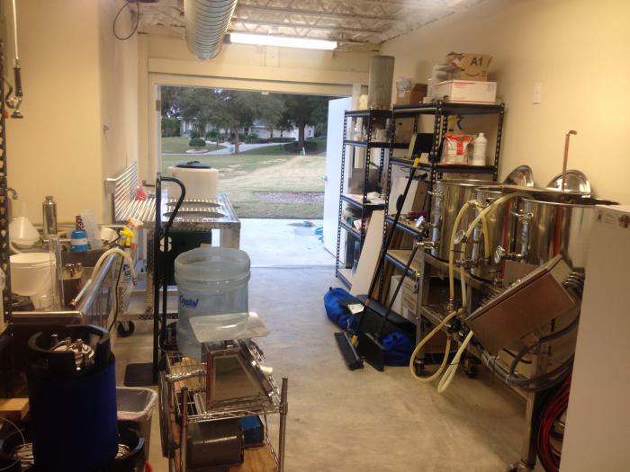
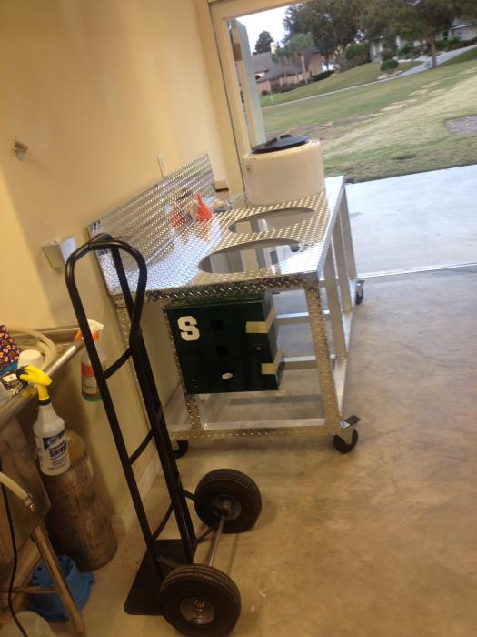
Delivered today. Fits nicely in the basement brewery. My friend took liberty with the control panel paint job. Good thing I'm a Spartan!

Can't wait to start putting it all together. Ordered the other two conicals today. Should have gotten on that sooner.

She rolls like a champ. Much lighter than the brutus rig done out of SS. I think I did 5" casters for this one.

I'm sure I'll have lots more questions, but for now, it in my court as far as putting it all together. A huge thanks to packet and the others who've helped with my questions. It seems getting the conicals airtight is the most difficult part. Is it easier to entirely remove the screwed in threaded flange for the lids and try to apply some sealant on the flat plastic OR just run a bead around the edge? I'm wondering if there is air leak through the screw holes?

More pics to come as I get it put together and some beer in it.

TD

IMG_1177.jpg


IMG_1178.jpg
 
I'm sure I'll have lots more questions, but for now, it in my court as far as putting it all together. A huge thanks to packet and the others who've helped with my questions. It seems getting the conicals airtight is the most difficult part. Is it easier to entirely remove the screwed in threaded flange for the lids and try to apply some sealant on the flat plastic OR just run a bead around the edge? I'm wondering if there is air leak through the screw holes?

Seal everything up below the lid. There's a rather large lip on there that will trap god knows what if you don't seal it up entirely.

The actual lid itself isn't airtight either. I've been thinking about working on another lid design entirely, but haven't figured out something workable yet.
 
Thanks


I've seen some folks fashioning a plexiglass type lid with an O-ring seal.
Airtight is best, but Bug-Tight is all I need. Have you been using the system for lagering for say 6 weeks post fermentation? Just wondering if that'd be a potential detriment of being bug-tight, but not air tight (like L. Pasteur's original bug proof flask.)

I have a food storage bin that uses this lid called the "gamma lid" for an airtight seal. Not sure if the dimensions fit so I could use on the conical. I know that it uses a threaded lid similar to the conicals but has a rubber O ring. as well. I bought a spare and I might see what size difference there is.

TD


TD
 
They're definitely bug tight. Not sure if the gamma seal lids would fit. Haven't tried to fit them myself.
 
Got the o ring the other day and the lid seals up air and water tight with just bit of pressure on the wingnuts. The spray pattern isn't impacted anymore by the threaded insert since it is removed and I also routered the recessed lip out of the conical to flatten out the inside top of tank. Hopefully will have the cooling coil thru the lid and back in it tonight. Now I wanna brew and see how it cleans up!


Click below for video.
 
wish I knew how to multi quote from multiple threads and posts...


TD


The only way I can see to do it is to go to your first quote. And copy it then go to the next quote you want and paste the one AFTER the first one the copy that page and go to the next. Etc.etc.


wish I knew how to multi quote from multiple threads and posts...


TD
 
Got the o ring the other day and the lid seals up air and water tight with just bit of pressure on the wingnuts. The spray pattern isn't impacted anymore by the threaded insert since it is removed and I also routered the recessed lip out of the conical to flatten out the inside top of tank. Hopefully will have the cooling coil thru the lid and back in it tonight. Now I wanna brew and see how it cleans up!

What kind of pump is that?

Nice! Can't wait to see how your chiller coils work.

Its funny that the shops selling these tanks online are sort of marketing that they are perfect for homebrew yet it seems are not entirely airtight.

I have some of that putty-like weatherstriping stuff in my garage from some previous project that I can't even recall. I am wondering if a little of that along the lip of the lid would give an air-tight result.

Your plexiglass/O-ring/Wingnut job looks great. I hope I can just use the lids as-is with a bit of silicone and some elbow grease.

Downstairs to do some more work on them now..

TD
 
What kind of pump is that?

Nice! Can't wait to see how your chiller coils work.

TD

http://www.marchpump.com/te-5-5c-md-ac/

It's scary when it kicks on and the little voice in the back of your head asks if that clamp is tight enough or if the silicone hose is going to pop off the barb.... I use less than a gallon to CIP with, but that's still enough to make a mess quick.

I've been using the cooling/heating coil since the second batch through the conical and it has been working great. Coldest I have been able to get it with two gallon milk jug ice blocks is 55* with no insulation on the conical. Been looking for a small chiller or some other way to drop the temp for crash cooling without having to change a milk jug every 8 hours.
 
I've been using the cooling/heating coil since the second batch through the conical and it has been working great. Coldest I have been able to get it with two gallon milk jug ice blocks is 55* with no insulation on the conical. Been looking for a small chiller or some other way to drop the temp for crash cooling without having to change a milk jug every 8 hours.

add insulation to the conical. It makes a gigantic difference. Mine went from having the A/C on 30min out of the hour to ~10 min out of the hour just by adding insulation to the conicals.
 
As I work on mine, the enclosure/control panel part, here are some suggestions for others doing this.

Be sure in planning the holes you drill out for the XLR connectors, that you leave ample spacing between the holes for tightening the nuts on the exterior of the enclosure. The enclousure spec'd out by packet is plenty big enough, so don't cram them too close together or you'll have problems.

When mounting the components in the enclosure, I found it to be easier to attach the wiring to the flange-mount electrical connections BEFORE installing into the enclosure itself. I gave myself about 12-18 inches of wire to make the connections. You just can't get a screwdriver on the these to lock in a wire once they've been installed.

Ditto on the XLR connectors that require soldering. Once all these are installed, THEN put the panel plate inside, with everything mounted and wired as much as possible before.

TD
 
Has anyone tried one of the custom 14 inch gaskets from Brewerygaskets.com on this conical to seal the lid properly? I ordered one tonight to give it a shot. It fits over the edge of the lid and "should" provide a proper seal.
 
Has anyone tried one of the custom 14 inch gaskets from Brewerygaskets.com on this conical to seal the lid properly? I ordered one tonight to give it a shot. It fits over the edge of the lid and "should" provide a proper seal.

Awesome! Let us know how that works! I haven't tackled that part yet.

Still working on the enclosure. Need to finish up the last few bits of wiring. I rather enjoyed this part once I got the hang of the DIN rails. By the way, one thing sort of bothers me about the driver board. It apparently has no - VDC connection? Only a +VDC and a GND. I've not tested it yet as I still have some work to do, however, seems odd.

Foam and last two tanks haven't arrived yet. Didn't want to start on the conicals until I have all three, as I figured it would go faster and take less overall time (Read as, this crappy weather is making me really lazy).

My cooler is a little too long to fit. Will work as I originally intended, but would be nicer if I could find one less than 22" wide to fit between the uprights. Would let me push the whole cart flush to the wall. Only coolers I could find are Yeti brand and hella expensive ($300 ish?) Less than 48 qts though. 35-36 QT I think...

I think I'll wait on the lids until I hear back from you about the custom seals.

TD
 
I received the seal yesterday. Bit fits perfectly on the top. However, you still have to take the inside threaded ring off to apply silicone as before. Luckily, I had already completed this task. I applied forced air from my compressor and it appears as if there are no leaks. The true test will come when I actually ferment in it. I will take a photo this afternoon and post
 
Thanks for sharing. Looking forward to the photos.. I'm sure if an air compressor won't make it leak, that fermentation will be fine.

TD


Sent from my iPad using Home Brew
 
Pricedawg,

I see two custom gaskets, lid seal 1/2" and lid seal 3/4", and you pick the outside diameter (14"). Which did you use? These are red silicone.

Thanks

TD


Sent from my iPad using Home Brew
 
I used the 3/4. It's a snug fit. Still allows room to screw the lid on and get plenty if grip.
 
Has anyone tried one of the custom 14 inch gaskets from Brewerygaskets.com on this conical to seal the lid properly? I ordered one tonight to give it a shot. It fits over the edge of the lid and "should" provide a proper seal.


I ordered a food grade o-ring from www.oringwarehouse.com. It's 1/4" and seems to work well. Can't remember what size it was offhand.


Sent from my iPhone using Home Brew
 
Be nice to see the O ring and the manway gasket pics when you have time to post them.

I believe all parts are now on hand and I'm ready to move forward with the conicals. Finding time to do this has been a challenge.

TD
 
@heckels,

When you screw the top on, does the o-ring stay in place? That is, the friction between the cover, the o-ring, and the base doesn't move the o-ring out of place? Do you lube it at all?
 
From what I've been able to tell it stays in place. Up to this point I haven't needed it to hold pressure so I haven't bothered with lube.

I looked up the size. I believe it was -454 (12.5 ID, 1/4"). It sits perfectly in the middle of the screwed down threaded ring.


Sent from my iPhone using Home Brew
 
Ahhhh.. Now I see... Thanks for the post! Where is the glycol coil or were you the guy that hadn't done that part yet?

Thanks!

I want to see the O-ring pics too and then when I get to the silicone sealing I'll see if I need any gaskets/O-ring...

TD
 
Back
Top