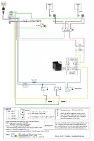
Single PID controlling HLT and BK

Homebrew Talk - Beer, Wine, Mead, & Cider Brewing Discussion Forum

Help Support Homebrew Talk - Beer, Wine, Mead, & Cider Brewing Discussion Forum:

This site may earn a commission from merchant affiliate links, including eBay, Amazon, and others.

bennieb

Member
Joined
Nov 22, 2010
Messages
8
Reaction score
0
Location
san diego
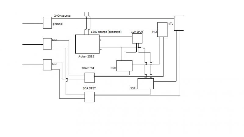
I am attempting to wire my kettle and HLT to one PID. Unfortunately I have only 3-wire 240v source so I am relying on a separate 120v source to power the PID. Any comments or suggestions on how to improve this simple design would be appreciated. The 12v dc spdt switch should allow me to switch between driving the kettle ssr and the hlt ssr. The PID is an auber 2352 and I plan to use manual control on the kettle and the hlt will have an rtd probe.
auber.jpg
 
I'll mention some things for you to consider. The Auber Instrument PID SYL-2352 can be powered from 85~264VAC/50~60Hz. With that said, you don't need the 120V power addition.

You are planning on running the HLT or BOIL so I would replace the 2 - 30A DPST switches with a single DPDT-center off grainger.com Toggle Switch 2TPF8 - or you could get this switch instead grainger.com Toggle Switch 2TNZ7 and replace all 3 switches with it. It is 3 pole double throw center off.

My only real concern with your setup is that you do not mention GFCI protection. I believe this is something critical as without it you will be playing 'you bet your life'. There is an easy way to accomplish that protection. Just buy and install this GE Spa Panel. It is well worth the $50 spent.

Hope this helps.
 
Some more thoughts for you:

Get the GE Spa Panel I mentioned and set it up to be plugged into your 240V outlet - like this:

power-panel-6.jpg


Then set up your controller this way:
(Click on the image to see a full scale diagram that is printable on Tabloid paper (11" x 17")


This way you only need one SSR and one heat sink for it. A bonus is that the whole thing will fit in the Project Box offered by Auber Instruments. Another bonus is that there is an Emergency Stop as well.

Hope this helps.
 
Just had a quick question, as I have been exploring electric brewing for the last few weeks...

What SSR/heat sink is everyone purchasing (i.e. part numbers, amps, volts, etc.). I understand the wiring diagrams (for the most part), and want to be safe in my electric ventures. Also, I would be interested in knowing which project box from Auberins is PJ referring to?

Everything else in any of the diagrams I have seen of PJ's make plenty of sense, I am just wondering about the part numbers, etc.

I have also been lurking on Tiber_Brew's build, and getting most of the part numbers from there, but I like the idea of a single PID controller at this time to at least get started with electric brewing.

Any help would be greatly appreciated, and if this has been answered in another thread, please point me in the right direction. I hate to hi-jack the thread, but I hope the answer is beneficial to everyone else too.
 
Thanks for the reply PJ (I was hoping this would see this!) I do have the gfci spa breaker that you mentioned (just forgot to say so in the op) and thanks for looking out for safety first. The wiring to the outlet is 4-wire but in my wisdom I installed a 3-wire outlet as I now only have the HLT element connected via a DPST 30a switch that I use to manually heat the HLT as needed. I agree that a DPDT switch to replace the two DPST 30a switches would be ideal but any of the DPDT switches that handle 30a (as both elements are 5500w) are $40+ dollars. Finally, I have seen a schematic that you have made similar to the one on this post and it really made me consider rewiring to 4-wire and following your drawing. If I dont change to 4-wire, how can I power the PID with a 3-wire 240v source? I thought I needed neutral plus one 120V leg and that ground cannot replace a neutral leg. Please correct me if I am wrong on this.
 
Just had a quick question, as I have been exploring electric brewing for the last few weeks...

What SSR/heat sink is everyone purchasing (i.e. part numbers, amps, volts, etc.)
...

This Excel sheet might help you -
Brewery_Parts.xls The 'URL' column will take you to the part listed.
Save to your computer (if you want) and then you can change it to fit your specific needs.

I hope it helps.

P-J
 
Just had a quick question, as I have been exploring electric brewing for the last few weeks...

What SSR/heat sink is everyone purchasing (i.e. part numbers, amps, volts, etc.). I understand the wiring diagrams (for the most part), and want to be safe in my electric ventures. Also, I would be interested in knowing which project box from Auberins is PJ referring to?

I purchased these but waiting for them to arrive:

http://www.ebay.com/itm/110734772193?ssPageName=STRK:MEWAX:IT&_trksid=p3984.m1423.l2649
 
Thanks for the reply PJ (I was hoping this would see this!) I do have the gfci spa breaker that you mentioned (just forgot to say so in the op) and thanks for looking out for safety first. The wiring to the outlet is 4-wire but in my wisdom I installed a 3-wire outlet as I now only have the HLT element connected via a DPST 30a switch that I use to manually heat the HLT as needed. I agree that a DPDT switch to replace the two DPST 30a switches would be ideal but any of the DPDT switches that handle 30a (as both elements are 5500w) are $40+ dollars. Finally, I have seen a schematic that you have made similar to the one on this post and it really made me consider rewiring to 4-wire and following your drawing. If I dont change to 4-wire, how can I power the PID with a 3-wire 240v source? I thought I needed neutral plus one 120V leg and that ground cannot replace a neutral leg. Please correct me if I am wrong on this.

Take a look at post #2. I linked to the switches and they are fairly inexpensive. 3 pole double throw is $16.33 at Grainger.

Regarding the wiring. Set up your Spa Panel as I show in the drawing post. Or change out the outlet to a 4 prong outlet.

P-J
 
P-J, I checked out those switches and they are rated for 15A at 240v and 25A at 120V. Will that suffice? I was thinking that the full amperage draw from the 240v element will be passing through the switch. - thanks for the help by the way!
 
P-J, I checked out those switches and they are rated for 15A at 240v and 25A at 120V. Will that suffice? I was thinking that the full amperage draw from the 240v element will be passing through the switch. - thanks for the help by the way!
Those switches are fine for our application as the voltage measured to ground from any point is 120V. Both 120V phases are open whenever the switch is off. It is more than capable of carring the current needed.

Hope this helps.
 
PJ - you are officially MY hero! I want my hobby to be safe, convenient, and enjoyable (in that order). I appreciate you taking the time to answer questions and be available to those of us who are learning electrical brewing systems. This will take me a while to acquire the pieces/parts for the build, but this gives me a great baseline for my future build. The parts list is extremely valuable; thanks for combining all the information in a very easy to navigate way. Your efforts will save me (and everyone else) a great deal of time!

BennieB - I am not quite sure if I even know what I am talking about, and feel free to educate me and correct me if I am wrong, but aren't those E-bay SSR's DC to DC? It appears that the Auber SSR's are DC to VAC (PID IN --> Control 3-32 VDC --> 40A 90-480 VAC 50-60HZ --> Output)? Again, please let me know if I am incorrect, as I am learning...
 
Take a look at post #2. I linked to the switches and they are fairly inexpensive. 3 pole double throw is $16.33 at Grainger.

Regarding the wiring. Set up your Spa Panel as I show in the drawing post. Or change out the outlet to a 4 prong outlet.

P-J

PJ - you are officially MY hero! I want my hobby to be safe, convenient, and enjoyable (in that order). I appreciate you taking the time to answer questions and be available to those of us who are learning electrical brewing systems. This will take me a while to acquire the pieces/parts for the build, but this gives me a great baseline for my future build. The parts list is extremely valuable; thanks for combining all the information in a very easy to navigate way. Your efforts will save me (and everyone else) a great deal of time!

BennieB - I am not quite sure if I even know what I am talking about, and feel free to educate me and correct me if I am wrong, but aren't those E-bay SSR's DC to DC? It appears that the Auber SSR's are DC to VAC (PID IN --> Control 3-32 VDC --> 40A 90-480 VAC 50-60HZ --> Output)? Again, please let me know if I am incorrect, as I am learning...

Good eye....i guess i can at least use the heat sinks.......
 
Just tossing out another option. If you are only going to be controlling either the HLT or BK at any point, what about outputting to a receptacle from the controller. You can then plug whichever unit you need to heat at that time. It saves you the switches and the second SSR. This is the route I'll be going, but that's largely because I'll only be starting with one tank and will add a dedicated HLT down the road.
 
I think this is probably where I'll start with my electric build. I plan on beginning with the HLT, because my current setup involves lifting hot water up into the top tier of my gravity-fed system. I will eventually make it all electric with pumps and a HERMS, but that is a way down the road.

I currently brew in a very large (3000 sq ft) shop with 14 foot ceilings, so I don't really need to conserve space, but I eventually want to be able to brew in my garage at the house, so the electric system will make that much better and safer in winter.

This diagram and the parts list you provide is perfect for what I'm trying to do. P-J, you are an incredible and incredibly generous man. Thanks for sharing your hard work with all of us.
 
SGFBeerBuzz,

It pleases me that it fits your needs.

Thanks a lot for the kind words and wishing you great success in your adventure.

P-J
 
P-J, I like the diagram. I would like to build one similar. I would like to have a led light for the HLT and one for the Bk. Could they be installed after the switch on one of 120v lines? Thx
 
P-J, I like the diagram. I would like to build one similar. I would like to have a led light for the HLT and one for the Bk. Could they be installed after the switch on one of 120v lines? Thx
How about this?

As always - Click on the image to see a full scale diagram that is printable on Tabloid paper (11" x 17")


Will this work out for you?

P-J
 
P-J and others, I have a question. I plan on using this exact system, even already picked up the stuff from Auber Instruments including the project box. My only concern is that I have a 50 amp service to the garage, where I plan to brew, and this system is set up for a 30 amp supply. (Also, I added a 50 amp gfci spa panel, for protection...) Would it be better to switch out the 50amp breaker in the main service panel or should I added a 30 amp dpdt circuit breaker in the brewery's control box? I'm thinking that, since I don't plan on using more than one heating element at a time it would be cheaper and easier to change out the circuit breaker in the main service panel... Any thoughts?

Thank you, Dan
 
borny said:
P-J and others, I have a question. I plan on using this exact system, even already picked up the stuff from Auber Instruments including the project box. My only concern is that I have a 50 amp service to the garage, where I plan to brew, and this system is set up for a 30 amp supply. (Also, I added a 50 amp gfci spa panel, for protection...) Would it be better to switch out the 50amp breaker in the main service panel or should I added a 30 amp dpdt circuit breaker in the brewery's control box? I'm thinking that, since I don't plan on using more than one heating element at a time it would be cheaper and easier to change out the circuit breaker in the main service panel... Any thoughts?

Thank you, Dan

If I were you I'd just fuse the power coming into your panel at 30 amps. Cheap and easy to upgrade in the future if/when you decide you need more.
 
That's what I'm thinking, that way I could add another 15/20 amp circuit in the spa panel for other accessories. But if I add circuit protection in the brewery control panel it should be a double pole breaker, not a fuses, correct? so if one side trips, they both will... I know this is redundant, but I'm just being cautious about the design....


Thank you,

Dan
 
Awesome thread! I first have to say thank you P-J for the wonderful schematics and thanks to HBT for the ompf I needed to get this started!


Also, sorry to hijack this thread! I will bow out now.

I just completed my panel today. The wiring is a bit out of control, but I will who pictures of the front and back. I will be adding a outlet plate cover, just haven't yet. And if I knew how to solder, I would solder the quick disconnect for the RTD...

ForumRunner_20120203_132142.jpg
 

Attachments

  • ForumRunner_20120203_132233.jpg
    ForumRunner_20120203_132233.jpg
    7 KB · Views: 320
Soldering is not hard and basic equipment is cheap and you can get it at any radio shack. I would look up a couple you tube videos on how to solder. And practice on some wire before you attempt it on your temp probe disconnect.
 
I too am planning on building the same system.

With regards to the RTD thermocouples, is this set up designed to handle only 1 RTD placed on the HLT.
If another RTD was in the boil pot how would that be wired to work properly? I suppose I could just plug and unplug from the HLT to the Boil.

PJ,
You are a very a kind and generous man with all of your electrical help on this forum. I don't think most of us could tackle projects like this without your willingness to help. For this I say thanks.

Dan

image-1850078245.jpg
 
Dan,
Thank you for the comments.

With the PID (Auberin SYL-2352) in the diagram, you do not need a temp probe in the boil kettle. The PID is switched to manual mode so that the power delivered is regulated to control the boil 'intensity'. Temperature at this point does not play in the process. Water boils at 212° at a raging boil or at a simmer boil. The rate just depends on the amount of power delivered. I firmly believe that the manual mode of the Auberin PID solves a huge issue here. Manual mode allows you to input element power from 100% down to 0%.

Just saying...
 
Thanks again PJ,
Thats what I thought but I needed confirmation from the expert(s):rockin:
Dan,
You are more than welcome and I'm glad that you posted your concerns and thoughts.

That gave me a chance to respond with info that could help you and others imbarking on this adventure.

Wishing you huge success.!
 

Latest posts

Back
Top