Controller Question for P-J

Homebrew Talk - Beer, Wine, Mead, & Cider Brewing Discussion Forum

Help Support Homebrew Talk - Beer, Wine, Mead, & Cider Brewing Discussion Forum:

This site may earn a commission from merchant affiliate links, including eBay, Amazon, and others.

O'Haggerty

Well-Known Member
Joined
Mar 2, 2008
Messages
71
Reaction score
0
Location
La Crosse
Or anyone who can give a solid answer to the following questions...

This thread was extremely helpful... https://www.homebrewtalk.com/f170/suggestions-controller-249400/index4.html

but the parts list excel file has multiple extra/unneeded options that I'm having trouble sorting through.

For starters,
- My build is for a 220v/30amp/3 wire power source run through a 50A GFCI spa panel into a controller box.

- The brewery electrical requirements consist of:
2x 5500W elements (HLT + BK, only running 1 element at a time)
2x 120v march pumps (running simultaneously at times)

- My controller box consists of:
auber 1/16 din controller project box
auber PID SYL-2352
auber 40A ssr + heatsink

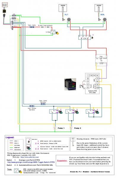
I am building my control box based off this wiring schematic from PJ:

wiringk.jpg


I have ordered the following with no issues:
- PID
- Project box
- 40A ssr + sink
- weldless RTD probe +QD mount
- yellow EPO switch
- 4 120v indicator LEDs (2 red for "element on", 2 blue for "pump on")


Ok finally my issues... the switches. You linked in the above thread that a 3PDT Toggle will be sufficient to switch/power either element plus feed the corresponding indicator light.

1) The specs say 25A@120V... 9A@240V... 9a isnt enough to power the element at 240v... am I just misunderstanding the amperage/leg or what? Can you confirm a link for the switch I need to order to accomplish this?

2) Also... according to the diagram the SSR only intersects one of the 120v legs... so if the PID/SSR is off, isn't the element still getting 120v from the other leg?

3) I want indicator lights for "pump on" for each of the pump toggles... which switch do I need for that action?

4) The connector to the element in the diagram is only 3 prong... wasn't the point to create 4 wire output? (through addition of an equipment ground/GFCI) Or do the elements just not receive a neutral?

I'm obviously no electrical expert but I'm very handy and feel comfortable taking on this project. I'll post any more questions that arise before powering anything up. Thanks for your help!

- Aj
 
I'm obviously no electrical expert but I'm very handy and feel comfortable taking on this project.

I....Like you
Had a bunch of questions.. And P-J, Helped and answered all..
By PM...E-mails and a couple of Hour long phone calls..
So until he jumps in here...
P-J drew a diagram for me , "AND I FOLLOWED IT TO THE TEE"
I want indicator lights for "pump on" for each of the pump toggles... which switch do I need for that action?

The switches #2,3 and 4 are illuminated switch.. If you use those.just pick color,push in it lights. I have and use them.

1) The specs say 25A@120V... 9A@240V... 9a isnt enough to power the element at 240v... am I just misunderstanding the amperage/leg or what? Can you confirm a link for the switch I need to order to accomplish this?

Thats a... NKK Mfr. Model #S33
I have and use that one

Also... according to the diagram the SSR only intersects one of the 120v legs... so if the PID/SSR is off, isn't the element still getting 120v from the other leg?

Looks wierd right... Stared at that for two weeks .
When you push the toggle to one side left/right ,
The SSR uses one leg and Second leg is straight from bus/terminal block.

Dont know if this helps...

attachments_2011_05_09.jpg
 
2) Also... according to the diagram the SSR only intersects one of the 120v legs... so if the PID/SSR is off, isn't the element still getting 120v from the other leg?

4) The connector to the element in the diagram is only 3 prong... wasn't the point to create 4 wire output? (through addition of an equipment ground/GFCI) Or do the elements just not receive a neutral?

The 240v element does not use a neutral wire. Neutral wires are only for 120v devices. You said you're using a 220v 3 wire power source. A 3 wire source is 2 hot wires and a ground, no neutral. If that is true than you won't be able to run your pumps. The diagram you posted shows a 4 wire power source.
 
The power source is converted to 4 wire 240 through the spa panel GFCI providing an equipment ground.... as I understand it anyway.

Thanks for the replies so far!
 
O'Haggerty,

Please give me a couple of days to provide (draw) a new diagram for you so that the whole thing is a little easier to follow. I'll also provide the parts sources.

Have you ordered the switch #1 yet? If not I have a cheaper solution usind a DP-Center Off-DT unit instead of the 3 pole.

Also with switches 2 - 4 there is a switch with built in indicator lights as shown if you want to go that route.

P-J
 
Or anyone who can give a solid answer to the following questions...
...
I have ordered the following with no issues:
- PID
- Project box
- 40A ssr + sink
- weldless RTD probe +QD mount
- yellow EPO switch
- 4 120v indicator LEDs (2 red for "element on", 2 blue for "pump on")

Ok finally my issues... the switches. You linked in the above thread that a 3PDT Toggle will be sufficient to switch/power either element plus feed the corresponding indicator light.

1) The specs say 25A@120V... 9A@240V... 9a isnt enough to power the element at 240v... am I just misunderstanding the amperage/leg or what? Can you confirm a link for the switch I need to order to accomplish this?

The switch is rated with reference to its case. It is switching 2 120V lines & in the configuration illustrated each switch contact will only have 120V with reference to the case (ground) as well as 120V across the contact when it is open. It's rating of 25A is appropriate in this situation.

2) Also... according to the diagram the SSR only intersects one of the 120v legs... so if the PID/SSR is off, isn't the element still getting 120v from the other leg?

It would appear so, however, there is no path for the electricity to flow.

3) I want indicator lights for "pump on" for each of the pump toggles... which switch do I need for that action?

The new diagram will illustrate that for you. (Although I'm presenting an illuminated push button switch, the wiring for an indicator light would be the same.)

4) The connector to the element in the diagram is only 3 prong... wasn't the point to create 4 wire output? (through addition of an equipment ground/GFCI) Or do the elements just not receive a neutral?

A 240V element is wired with 240V (2 120V phases) and equipment ground. The neutral in not used or wired to the element.

I'm obviously no electrical expert but I'm very handy and feel comfortable taking on this project. I'll post any more questions that arise before powering anything up. Thanks for your help!

Please give me a couple of days to provide (draw) a new diagram for you so that the whole thing is a little easier to follow. I'll also provide the parts sources.

Have you ordered the switch #1 yet? If not I have a cheaper solution usind a DP-Center Off-DT unit instead of the 3 pole.

Also with switches 2 - 4 there is a switch with built in indicator lights as shown if you want to go that route.

Ok. A new diagram. I've changed switch 1 to a double pole center off unit as the wiring for the indicator lights can be accomplished using it. It's also cheaper. I've also illustrated a flashing buzzer for use with the timer.

As always, click on the image to see a full scale diagram that is printable on Tabloid paper 11" x 17":


I hope this helps.

P-J
 
The power source is converted to 4 wire 240 through the spa panel GFCI providing an equipment ground.... as I understand it anyway.

Thanks for the replies so far!

I'm curious how this works. If you have 2 hots and a ground going into the GFCI how do you get 2 hots, a ground, and a neutral coming out? Can someone else chime in and explain it? I'm having a hard time understanding.
 
I'm curious how this works. If you have 2 hots and a ground going into the GFCI how do you get 2 hots, a ground, and a neutral coming out? Can someone else chime in and explain it? I'm having a hard time understanding.
It boils down to 'pre 1995 NEC code' that it is not 2 hots and a ground.!

It is 2 hots and a neutral. Using that info (AFTER) an outlet there is an opportunity to develop a '4 wire' system from that.

The key is the building wiring vs the plug in wiring..
 
Thanks so much PJ. Parts are on order and I'm thrilled to know I will never be forced to brew a propane batch again. I'll probably have some questions during the build so I hope bothering you once or twice more is ok. This is one of those projects that needs to be triple checked to be safe.

I'll post some pics of the build. Nothing too special but I can't wait to brew electric.
 
Well it was a work intensive and somewhat frustrating build but it's about finished! I've done 2 brews on this system and it's just ridiculous how fast and easy this electric setup makes brewing. (project was frustrating mostly because the home depot guy sold me the 10/14 gauge stiff wire used to wire houses instead of the flexible wire used in electronics projects.... ugh what a nightmare).

Here are some pics of the finished project (just an electrical retrofit... the 3 keggle herms was already in use prior).

Pics of the finished control box. Operates 2 (only 1 active at a time) 5500W camco ripp ulwd elements and 2x (simultaneous) march 809/120v devices from a 30amp 240v dryer plug.
IMAG0394.jpg

IMAG0395.jpg


The brewery (always a build in progress)
IMAG0396.jpg

IMAG0398.jpg

IMAG0399.jpg

IMAG0401.jpg


Overall I love it! Thanks so much to PJ and Kal for inspiration and guidance on this thing.

One issue though... I followed that last wiring diagram and I'm having an issue with the PID. Maybe I havent calibrated it correctly, but it seems like no matter what output% I set in manual mode for the BK... that the boil is 100% power anyway. Also, in auto mode when I set 169 deg F, the HLT heats to that level and just keeps heating. I have heard others talk of these issues with their Auber PID as well... so maybe theres a solution out there I just havent seen it. Anyone know whats up?

Thanks!
 
You need to program the PID:

4.2.3 Manual/Automatic mode switch
Bumpless switching between PID mode and Manual mode can be performed
by pressing the A/M key. The A-M LED will light up when the controller is in
Manual mode. In Manual mode, the output amplitude can be increased or
decreased by pressing ▲ and ▼(display mode 2).
Please note that manual control is initially disabled (A/M=2). To activate
the manual control, set A/M=0 or 1.

From the Auber Instruments PID manual

Please take a look at the manual.

BTW, your rig looks great!
 
You need to program the PID:


From the Auber Instruments PID manual

Please take a look at the manual.

BTW, your rig looks great!

Thanks! I like it. And btw, I had read those sections and enabled manual by setting A=0 and A=1. Still no regulating of current... it's like the SSR is stuck closed. I can't find any other programming or calibration hints.
 
Thanks! I like it. And btw, I had read those sections and enabled manual by setting A=0 and A=1. Still no regulating of current... it's like the SSR is stuck closed. I can't find any other programming or calibration hints.
Try removing one of the PID to SSR control wires and see what happens. If the element still heats then for sure the SSR has failed.
 
I got a new SSR with new heatsink... and also tweaked settings some more. It's working now.... but I'm not sure which was the culprit.

Point is... it's working flawlessly and I absolutely love the temp hold feature. Now I just need to make an app from my android phone to boot up my strike water on my way home and have it ready 30 minutes later when I get there....

Thanks again for your help PJ... this system is turning a lot of heads now... and I'm actually craving and loving brewing again... something I had lost for a while.
 
One comment about a 4 wire setup. Take the panel cover off of your electrical service and you might see that the white neutral wire is on the same lug as the ground wire. Further more only 3 wires come off the transformer that feed your house, 2 hots and a ground, just depends where the neutral and GND are bonded together at. Separating the neutral and ground wire I think is for the GFCI to work better in the event of an internal fault. GND and Neutral are the same potential separating them adds to better user protection from shock.
 
Back
Top