March pump wiring to switch/outlet

Homebrew Talk - Beer, Wine, Mead, & Cider Brewing Discussion Forum

Help Support Homebrew Talk - Beer, Wine, Mead, & Cider Brewing Discussion Forum:

This site may earn a commission from merchant affiliate links, including eBay, Amazon, and others.

Lind13

Well-Known Member
Joined
Mar 23, 2011
Messages
106
Reaction score
1
Location
Portland
Hey guys! I am sorry if any of you think this is a repost but after a few days of research and failed discussion with homedepot employees i am reaching out to you guys. I have essentially the same set up as this video

And i want to wire up the exact same switch box, but i have no flipping clue how i would do it. And the guys at homedepot were of no help. If this configuration is too difficult then tell me! I am really in need of wiring it up to use it as my other pump dropped and broke.
Thanks in advanced!
 
Last edited by a moderator:
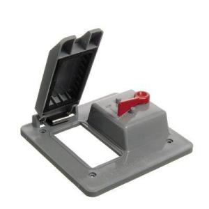
Piece of cake: Home Depot sells the Carlon series of PVC outlet boxes and the matching series of faceplates. You'd need a two gang box and one of these
db9bbf28-9931-433f-8148-e01b2bb4d974_300.jpg


Stick a GFCI outlet and a toggle switch in the box, slap on the faceplate, and you're good to go. The outlet comes with an instruction sheet that should show how to wire it, but if you're stuck, come back and ask for help...

Cheers!

[edit] Aw, slow morning, so I whipped up this sketch...
gfci_switched_outlet.jpg
 
What day trippr posted is perfect...The GFCI will have one side labled as "LINE" and the other side as "LOAD" you would place all your incoming power connections on the LINE side as his picture shows.....then hook up the pump to the LOAD side of the GFCI and your good to go.This way the GFCI and the pump are both switched ON/OFF
If you wanted to have only the pump on the switch then the black wire coming in from your power source will go to the LINE side of the GFCI instead of the switch as pictured, and theres usually two spots on those GFCI's for wires. The second spot on that same side of "LINE" you will hook up a small jumper wire and feed the switch and then hook up the pump to the switch.
 
[...]
If you wanted to have only the pump on the switch then the black wire coming in from your power source will go to the LINE side of the GFCI instead of the switch as pictured, and theres usually two spots on those GFCI's for wires. The second spot on that same side of "LINE" you will hook up a small jumper wire and feed the switch and then hook up the pump to the switch.

For the sake of clarity, in that configuration the input plug black and white wires must connect directly to the GFCI LINE side, the switch would take its power from the GCFI LOAD side black wire connection, the pump black wire goes to the other side of the switch, and the pump white wire must go to the GFCI LOAD side white wire connection...

Cheers!
 
Haha this is all still over my head but i believe with that diagram i could find what i need! Im a college student so you would think im smart enough to figure it out : / but i think ill get it! I was hoping to find someone with an inventory list of what they made theirs of but i think you two have given me enough! Thank you!

Would i need to buy an extension cord and strip the female end out to connect to the LINE side?
 
[...] Would i need to buy an extension cord and strip the female end out to connect to the LINE side?

You would cut the female side off the extension cord and toss it. Then strip the black, white and green wires and wire them as shown in either diagram: the one I posted earlier switches the outlet, which you can plug your pump into without modifying it; or this one, where the outlet is always "hot" and you would have to cut the end off your pump power cord and wire as shown...

gfci_switched_outlet_2.jpg


Cheers!
 
Which should i do if i am looking to turn the pump on and off with the switch on the box,and have the extra port on that box be "hot" for plugging in other things?
 
Which should i do if i am looking to turn the pump on and off with the switch on the box,and have the extra port on that box be "hot" for plugging in other things?

I've never seen a dual outlet GFCI that had independent sockets (and I can think of at least two good reasons why). So I suspect you'd have to go with a standard, non-GFCI outlet to do that, not something I would recommend.

That said, if you have the space you could add a single gang box with a standard outlet, wired to the LOAD side of the GCFI via the switch. That would leave the GFCI always hot and available for random stuff, while providing the GFCI-protected switched standard outlet for your pump(s).

If you need a diagram for that, just ask...

Cheers!
 
You would cut the female side off the extension cord and toss it. Then strip the black, white and green wires and wire them as shown in either diagram: the one I posted earlier switches the outlet, which you can plug your pump into without modifying it; or this one, where the outlet is always "hot" and you would have to cut the end off your pump power cord and wire as shown...

gfci_switched_outlet_2.jpg


Cheers!

So I wired my pump like the diagram above and the pump will not turn on. I am looking to have the outlet always hot and have the pump turn off and on with the switch. The GFCI has power to both outlets but the switch will not turn on the pump. Any suggestions?
 
Take some pictures of your work and post them. Then we can help you diagnose this. I use two separate switches plugged into on receptacle to run my pumps. All the switch needs to do here is either complete the circuit or break it
 
Im using a 2 way switch. from the pump i have the white going into the load side of the GFCI and the black goes to the switch. the switch has a jumper for the black going to the load of the GFCI. For the power i have black and white to the line of the GFCI. All the grounds aretogether and attached with a wire connect, if you see an extra white wire in the pics its a jumper i used for one of the grounds. Does it make a difference which holes in the back of the GFCI the wires go in on the load and line side? What about on the side of the switch? I understand completely that the switch is just opening or closing the circuit to power the pump, its not too difficult figure...thats why im so confused. Could it be a faulty switch? will the pump turn on if it does not have any liquid going to it?i
I apologize for the crappy pics

IMG_20120317_070519.jpg


IMG_20120317_071352.jpg


IMG_20120317_075026.jpg
 
The diagram is bulletproof if you follow it precisely. Which means hooking the GFCI LINE side to your line cord with the male 3 prong plug, and the pump and switch to the LOAD side.

Take a real close look at the GFCI. It should have LOAD and LINE text molded into the shell. Then switch your wires around accordingly.

But, if by some chance you do have the wiring correct, take the switch out of the equation and temporarily hard-wire the pump black wire to the black wire from the GFCI LOAD side. If the pump spins up when you plug in the line cord, you had a bad switch....


Cheers!
 
I would unwire the pump and see if your wiring to the switch will control the outlet itself by plugging something in. Also make sure you have not tripped the gfi and it needs to be just reset. Once you know your outlet works, you need to make sure your pump is then wired downstream from the power source in order to get the gfi protection.
 
I appreciate everyones help. Im starting to think its the pump. Ive tried wiring it directly through the outlet and bypassing the switch and it will not run. The GFCI has power to it since i can plug stuff into it and they have power. I might have to contact AHB and see it they have any suggestions since i bought it from them one Ebay.
 
Take the 4 phillips screws off the pump head and try running it motor alone....at least it will narrow down where the issue is if its the pump...
 
So when i wire the pump directly to the plug it will run...so im doing something wrong with the wiring.

Could it be my choice of GFCI and/or the switch? Does it make a difference what kind you buy? The GFCI is http://www.homedepot.com/webapp/wcs...eId=10051&catalogId=10053&productId=202026815

and the switch is a basic 2 way 15A 120V. I might take it into to work tomorrow and have some of the guys there take a look at it
 
Are you certain that you have the wiring to the GFCI correct, that the line cord is wired to the LINE side and the switch is wired to the LOAD side?

Cheers!
 
Ok, that looks good. Have you tried bypassing the switch and wiring the pump's black wire directly to the GFCI load side? That'd be the next step in debugging the problem...

Cheers!
 
Ok, that looks good. Have you tried bypassing the switch and wiring the pump's black wire directly to the GFCI load side? That'd be the next step in debugging the problem...

Cheers!

i did try that and the pump did not run. the only time it runs is when i wire it directly to the plug
 
i did try that and the pump did not run. the only time it runs is when i wire it directly to the plug

So your wiring diagram looks correct, and you've said the sockets on the GFCI are in fact hot, but wiring the pump to the load side outputs provides no joy regardless if you have a switch there or not.

If all that is correct, the GFCI must be at fault...

Cheers!
 
Okay, my turn for a wiring question.

I want to wire an extension cord directly to a gfci to power my rims system.
In the same box I have a switch that will control my march pump only. There will also be power diverted up to my controller box. Gfci will remain hot at all times once extension cord is plugged into house outlet.

Is this correct?
Remove female plug from extension cord. Wire into line side of gfci.
Wire pump to load side of gfci with switch on black wire.
Wire to controller box also out of load side of gfci.

Sorry no diagram. If you have time to work one up, I'd appreciate it.
 
Jon73, if you wire it up to the load side then the GFCI will be acting as a circut breaker. If thats your intent then you should be just fine...but if it tripps then your entire system will go dead. If thats not what you want then split the leads off the ext.cord into 3 legs....one going to the GFCI...the other going to the switch to control the pump...and the 3rd to the control box.
 
Running a branch around a GFCI pretty much obviates the reason why people incorporate such a safety device in the first place.

I would - and have - run everything on a brew stand through a GFCI. It is not a load sensitive device. If it trips, it's because not all of the return current is traveling through the neutral wire. Which means something is seriously amiss, and shutting the whole rig down is the safest response...

Cheers!
 
re: jon73...your plan sounds solid, you should be good to go. It's essentially the same wiring as was previously discussed, with the addition of an unswitched parallel circuit on the load side of the GFCI to power your control box...

Cheers!
 
Thanks for the help. I kind of knew how to do it, but needed to be certain.
 
This was a very helpful thread. I followed the revised schematic drawn up by day_trippr and it worked flawlessly. I have my pump on the switch with the GFCI plug always hot. Since I already had a heavy duty 12 gauge 100' extension cord, I cut about a foot off the female end and rather than tossing it as suggested, I used that to connect into the box on the load/switch side. That way, I can unplug and service the pump as necessary, or use the whole switchbox apparatus for other things (like getting power out to my Tuff Shed. Thanks again, guys. :ban:
 
Can someone link to the correct Switch somewhere online? Looking for one like in the first post of this thread.

Thanks.
 
Simple way to switch it is by using a GFI strip and using the strip power as the switch.
 
Back
Top