jsguitar
Well-Known Member
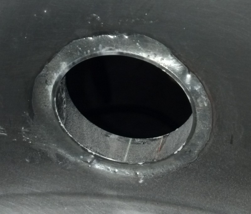
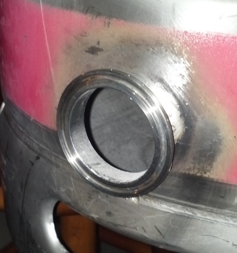
I got it out.
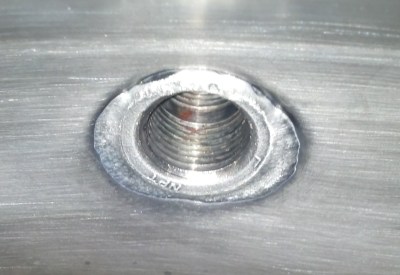
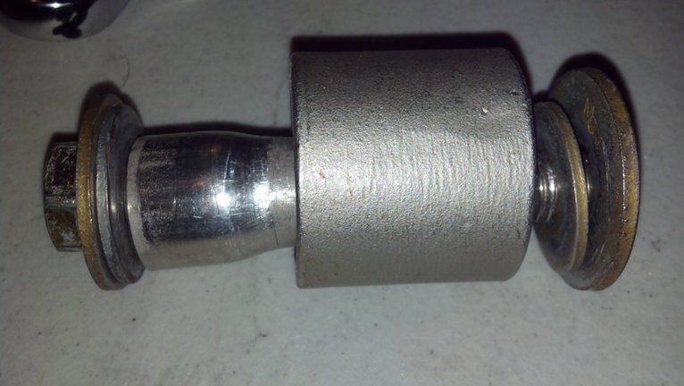
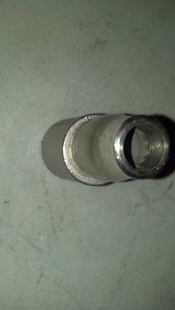
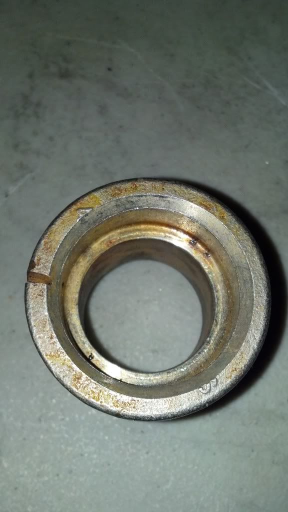
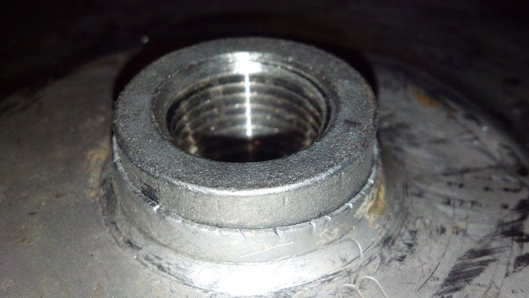
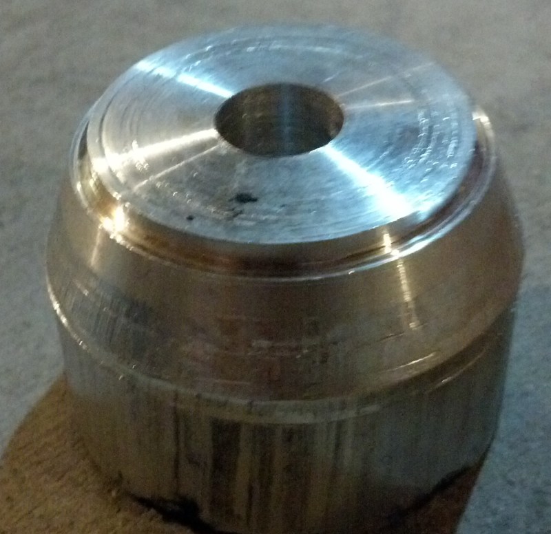
I got the dimple tool ready to go. I had a rag with some flux on it ready. I heated it until the solder started melting and wiped the joint on the inside, heated and wiped, put the tool in as fast as I could and started cranking and it budged pretty easily. I have a little clean up to do but not too big of a deal.
I got the dimple tool ready to go. I had a rag with some flux on it ready. I heated it until the solder started melting and wiped the joint on the inside, heated and wiped, put the tool in as fast as I could and started cranking and it budged pretty easily. I have a little clean up to do but not too big of a deal.
")