Question about Wiring Diagram (coils)

Homebrew Talk - Beer, Wine, Mead, & Cider Brewing Discussion Forum

Help Support Homebrew Talk - Beer, Wine, Mead, & Cider Brewing Discussion Forum:

This site may earn a commission from merchant affiliate links, including eBay, Amazon, and others.

smoothlarryhughes

Well-Known Member
Joined
Nov 10, 2010
Messages
117
Reaction score
1
Location
Collegeville
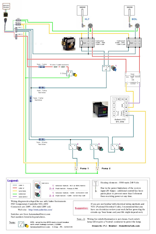
I was wondering what the use of the coil in the second diagram does? I've seen some wiring diagrams that use coils, and others that do not.

Auberin-wiring1-a17e--SYL-2352-5500w.jpg


Auberin-wiring1-a4-5500w-30a-e-stop.jpg
 
I drew the diagrams that way because that is what the brewer wanted when I drew it.
The issue becomes the type of switch used that will handle the current draw feeding the heating elements.
The toggle switches used in the first diagram must be rated at a minimum of 25A on each leg.
The second diagram using contactors (coils) allows a completely different switch to be used.
In that case it is an illuminated switch that cannot carry more than 10 amps.
The switch controls the contactor which in turn switches the high current being delivered to the element.

Hope this helps.

P-J
 
Thanks P-J...that helps alot. I was wondering if you could adjust the first wiring diagram a bit for me to include a second PID. I am looking to have one PID to show me the HLT temperature and control the HLT and brew kettle, and a second PID to show the mash temperature. What terminal strips and indicator lights do you recommend to use?

Thanks

Jim
 
Jim,

I'm not understanding your plan. Why a PID to just show the mash temp?

Hmmmm. We need to talk. (PM me and I'll call you.)

P-J
Paul
 
I believe Kal uses a PID for the HLT to monitor the water temperature in the HLT, and also has a separate PID for the mash tun. This is what I'm looking to do, but I do not want a 3rd PID for the boil kettle because I don't see the need to know the temperature in the boil kettle, when I can just use manual mode on the HLT/BK PID. My plan is exactly like this diagram, but with a second PID for the mash.

Hopefully this is more clear for you. I'll PM later on as I'm off to work...hopefully this clears it up for you in the meantime. Also, for the terminal strips...I'd assume they have to be rated for 30A or above.

Thanks,

Jim

Auberin-wiring1-a17e--SYL-2352-5500w.jpg
 
Ok... I understand what you are trying to accomplish.

Something to keep in mind though, you will be laying out about $100 more just to monitor the temp in the mash tun. Which, by the way, might be accurate on not depending on many factors.

Just saying.

P-J
 
P-J saved me a few bucks by not putting a PID/Temp probe/fitting/etc and all the wiring, parts, etc to make it all work, just to monitor mash temps. I have a dial thermometer that gives me a look at the temp of the wort coming out of the MLT on its way to the HERMS coil.

I honestly think that even watching that can add confusion (maybe even stress). If the temp is too low, I have a tendency to want to crank the temp of the HLT to pick up more heat from the HERMS coil. Then I overshoot as the hotter wort is dumped on top of the mash and it takes time for that warmer wort to get to the bottom and pass over the thermometer again.

If you're doing a HERMS or RIMS system, trust your equipment. If you use a HERMS system, set your HLT a degree or two above your mash temp and leave it alone. It will never overshoot if you let it do its job. If you can do your part to use the proper temp on your strike water, the rest of the mash should be set it and forget it, especially if you're recirculating.

P-J will help you get where you want to go and he'll help you avoid spending money on stuff that's not necessary, unless you insist on it.
 
Thanks for all of your opinions...I just thought it might be good to know the actual temperature inside the mash, but I guess I could just get to know how many degrees to set the HLT above mash temp I should be fine.

PJ...do you have any specific indicator lights you recommend that are wired off of the BK/HLT switch? Also...I see you are using push button switches for the pumps and the PID power...I assume I can replace these with my switch of choice, as long as they are rated 15A/120V?
 
Thanks P-J..I missed that on the drawing. One last question for you...as I've decided to go with the exact drawing you have above with the timer. This switch (on/off/on) is rated at 250V/15A...and since it has both hots going through it to the elements, wouldn't it need to be rated for 250V/30A since the elements pull over 20A?

http://www.grainger.com/Grainger/ww...ch&Ntt=2tny6&N=0&GlobalSearch=true&sst=subset

Looking to order my parts soon and get this build started.
 
The switch is ok with the circuit as it is drawn. Keep in mind that both legs of the 240V's are switched at the same time so that there is never 240V present across the switch contacts.
 
Thanks...what is the min rating on the selector switches that I would need? I see the ones on auber are rated for 10A, and I've seen some on ebay rated at 6A. I'd be using these for the pumps and the PID switch only. And the indicator lights only need to be 120VAC correct?
 
I'll most likely go with the auber switches rated at 10A...just a quick question...what would happen if something that was plugged into the pump outlets was pulling more than 10A, if the breaker is a 30A breaker? Not saying I would be plugging anything into these outlets besides pumps...but just curious.
 
Please take another look at any one of the diagrams you referenced in this thread. In every case there is a fuse in place to protect the outler wiring.
 
Back
Top