Monitoring/controlling with Linux on the cheap

Homebrew Talk - Beer, Wine, Mead, & Cider Brewing Discussion Forum

Help Support Homebrew Talk - Beer, Wine, Mead, & Cider Brewing Discussion Forum:

This site may earn a commission from merchant affiliate links, including eBay, Amazon, and others.
As the actual temp approaches boiling, the sensor reports about 180º F. I used slow cure epoxy.

Well, I don't have a sensor in my boil pot so I can't speak to those temps. I've been using these things for years and never had an issue, but, none of my previous applications work at boiling temp (e.g. my house has 1 in each room). As previously mentioned, the accuracy spec for these is up to 85C (and you know what temp boiling is).

Slow cure is much less susceptible to bubbles than fast cure, so I'd guess that reduces the chances this is the problem. However, I'm still a bit suspect. Air is a wonderful insulator and you're reading temps that are way low...
 
I'm boiling some water this morning for a yeast wash, so I put my HLT temperature probe in my pot of water and monitored it:

boiling.jpg


I came to a boil at 209 and change. The analog temperature probe in the boil pot read 208 during same time frame. While getting to that 209, the analog and sensor agreed within a fraction of 1 degree (the analog is too imprecise to tell for certain by how much).

If you're seeing wildly inaccurate temps, it's not due to the sensor accuracy. It's some other problem that needs to be solved.
 
Why are you guys using the 18s20 sensors? I was under the assumption that 18b20 sensors are more accurate. Im on my tab now so i dont have the datasheets in front of me but its worth a look. Replacing the sensor could fix the inaccuracies with high temps.

Edit:
Here's some notes from maxim, comparing the two:
http://www.maxim-ic.com/app-notes/index.mvp/id/4377

They recommend the 18s20 only for old designs, as the 18b20 is much more flexible, newer and recommended for all new designs.
 
hrafnkell said:
Why are you guys using the 18s20 sensors? I was under the assumption that 18b20 sensors are more accurate. Im on my tab now so i dont have the datasheets in front of me but its worth a look. Replacing the sensor could fix the inaccuracies with high temps.

Edit:
Here's some notes from maxim, comparing the two:
http://www.maxim-ic.com/app-notes/index.mvp/id/4377

They recommend the 18s20 only for old designs, as the 18b20 is much more flexible, newer and recommended for all new designs.

They both are accurate to 0.5 C. I use 18s20 because I didn't know about 18b20 at the time. I actually just bought some 18b20 and I am rewriting my arduino code for them.
 
I use the "s" model because that's what I have, and they work great for me (and it's hard to teach old dogs new tricks?). There is no difference in flexibility when using OWFS - it handles the low level bit twiddling. :)
 
Yeah my point exactly - there is no difference when using OWFS, but 18b20 is faster (you can poll it more often). It's also a newer design, so possibly it will solve your issues when measuring temperatures close to boiling.
 
I agree that this should help those with troubles at 100c using the "s" (and duh, why didn't anyone think of this before), but, don't get too caught up in that datasheet. Those read times are max values - not actual. In practice, you can read either unit as often as needed for this application. I doubt anyone here is looking for sub-second accuracy. :) I poll multiple probes in my process, and none are faster than once per minute. YMMV.
 
I was looking at the datasheet for the 18b20 and it said if you are measuring temps close to 100C you should use external power. Not sure if those reporting issues with high temps are using parasite power mode or not....
 
I was looking at the datasheet for the 18b20 and it said if you are measuring temps close to 100C you should use external power. Not sure if those reporting issues with high temps are using parasite power mode or not....

Good information. I'll have to check that when I get back into this stuff.


FYI - My Arduino comes in the mail today... :ban:
 
just as I was about to order a BCS-462. Right now all I want to do is monitor some temps, so I thought I'd give this a whirl.

Resurrected an OLD Presario 1800 laptop (1ghz Pentium III, 384MB Ram, 20Gb HD) and finally got a highly stripped-down version of Debian 6.0.4 running LXDE the way I wanted it. Installed Chrome, FUSE and OWFS, and found a program called digitemp that also looks promising. Ordered some parts from iButtonLink, and am just waiting to try it out.

:ban:

Also just ordered an Arduino Uno and ethernet shield for giggles.

Update 05/18/2012:

Well, the iButtonLink probe is too large for my theromowell, but the software works just fine.
 
Well, I got owfs, and owserver working finally. Seems that if you are using an iButtonLink LinkUSB, you have to use the --link=/dev/ttyUSB0 switch in order to properly communicate with the master. So far I've got a single temp sensor ( all I've got right now :eek: ) displayed in text on the localhost webpage on my old laptop.

I also got the sensor working on my arduino/ethernet shield, and am basically displaying the same info on that systems mini-webpages as well.

Man, it's been YEARS ( actually over a DECADE :drunk: ) since I've done any hardware prototyping or coding. It's fun, but I really don't miss the daily grind.
 
total noob questions:

I'm coming at this project from a perspective with a background in high-level programming and a dearth of understanding about hardware components, but I'd like to try my hand at this.

I get that we need a temperature sensor that relays signals on the main bus, and that signal needs to be sent through a 1-wire usb/serial adapter so it's accessible from the *nix box's filesystem... Everything from *nix to the displaying of data is kosher for me (I mostly do web dev)...

But everything that happens in between is a mystery to me. For instance, what is the purpose of the DS2406 component? I can't just basically connect the 1-wire temp sensor directly into the USB adapter and get a reading?
 
Well, I got 4 more temp sensors from Brewers Hardware, got the Arduino/Ethernet Shield running with the OneWire library, and got the Steel Canvas code setup, and all running from the Arduino\Ethernet\SD card:

ArduinoEthernetRadial.png


Almost out of codespace, but it's fun. :rockin:
 
Well, I got 4 more temp sensors from Brewers Hardware, got the Arduino/Ethernet Shield running with the OneWire library, and got the Steel Canvas code setup, and all running from the Arduino\Ethernet\SD card:

ArduinoEthernetRadial.png


Almost out of codespace, but it's fun. :rockin:

Neat canvas work. I've done some canvas and svg front-end for work in the past. It's a lot of fun.

Would you mind explaining a bit more about your setup? I'm wondering if perhaps I should go the arduino route myself, or go with the components outlined in the original post.
 
Neat canvas work. I've done some canvas and svg front-end for work in the past. It's a lot of fun.

Would you mind explaining a bit more about your setup? I'm wondering if perhaps I should go the arduino route myself, or go with the components outlined in the original post.

It's all sitting on my workbench right now, I've got it all hooked up to a little breadboard just to test it. Right now I'm using an Arduino Uno, an Ethernet Shield, and a 4gb micro SD card. The code creates six web files that allow me to select either 100, 150, 200, 250, 300, or 350 pixel gauges. I also create a simple web page that just displays the temps in text.

I'm planning on using RJ45 plugs and a rewired RJ45 patch panel for the hookup. I use Powerline networking to bring the ethernet outside for the time being, and am keeping my eye out for a WiFi shield. I eventually plan to use several of the units to monitor my fermentation chambers, beer and wine storage coolers and my "Barney"brewstand.

I have several linux boxes (zoneminder, seven recording channels / 6tb distributed mythtv) running around the house, so I use one of them to serve the javascript library files, as it takes forever (in terms of computer time :drunk: ) to get them from the arduino SD card.

I'm also getting an Arduino Mega, for the larger codespace.

Here's the code, for anyone that's interested. Most of it is just massaged from examples from the arduino playground, and xml code stolen from Bobby_M :rockin: :
Code:
/*

 * SD card attached to SPI bus as follows:
 ** MOSI - pin 11
 ** MISO - pin 12
 ** CLK - pin 13
 ** CS - pin 4
 */

#include <SD.h>
#include <OneWire.h>
#include <SPI.h>
#include <Ethernet.h>

/*********** SD Stuff ****************/
// On the Ethernet Shield, CS is pin 4. Note that even if it's not
// used as the CS pin, the hardware CS pin (10 on most Arduino boards,
// 53 on the Mega) must be left as an output or the SD library
// functions will not work.

const int chipSelect = 4;

/*********** ETHERNET STUFF ***********/
byte mac[] = { 0xDE, 0xAD, 0xBE, 0xEF, 0xFE, 0xED };
byte ip[] = { 192, 168, 1, 177 };
EthernetServer server(80);
#define BUFSIZ 100

/********** OneWire Stuff ************/
OneWire  ds(9); // OneWire bus on pin 9
float celsius[10], fahrenheit[10];
int cnt=0, maxCnt;

/********** Radial Stuff ************/
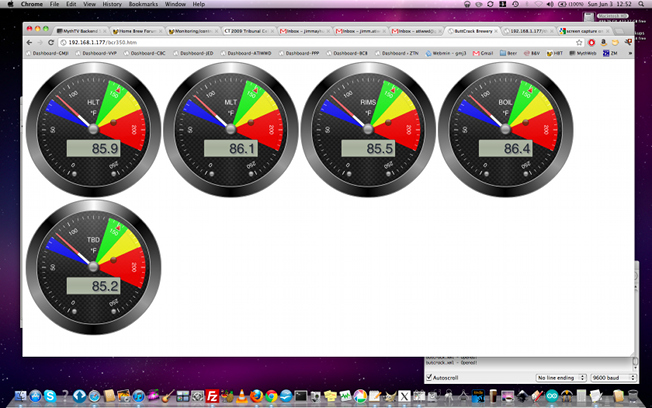
char *bcname[]={"HLT","MLT","RIMS","BOIL","TBD"};
char *bcrfn[]={"bcr100.htm","bcr150.htm","bcr200.htm","bcr250.htm","bcr300.htm","bcr350.htm"};
int bcrsize[]={100,150,200,250,300,350};

void setup()
{
 // Open serial communications and wait for port to open:
  Serial.begin(9600);

//  Serial.print("Initializing SD card...");
  // make sure that the default chip select pin is set to
  // output, even if you don't use it:
  pinMode(10, OUTPUT);
  
  // see if the card is present and can be initialized:
  if (!SD.begin(chipSelect)) {
    Serial.println(F("Card failed, or not present"));
    // don't do anything more:
    return;
  }
//  Serial.println(F("SD card initialized."));
 
 // set up bcradial.htm
 
 byte addr[8];
 
  while ( ds.search(addr)) {
    cnt++;
    delay(500);
  }
  
  ds.reset_search();

//  Serial.println("No more addresses.");
//  Serial.println();
  maxCnt = cnt;
  cnt=0;
 
//  Serial.print(F("maxCnt = "));
//  Serial.println(maxCnt);

// create radial canvas files

//Serial.println(sizeof(bcrsize)/sizeof(int));

for(int cnta = 0; cnta < (sizeof(bcrsize)/sizeof(int)); cnta++)
{
  SD.remove(bcrfn[cnta]);
  writeBCRfile(bcrfn[cnta], bcrsize[cnta]);
}

  // now start up the webserver
  Ethernet.begin(mac, ip);
  server.begin();
//  Serial.print(F("Ethernet server is at "));
//  Serial.println(Ethernet.localIP());
  
}

void getOneWire(void)
{
  byte i;
  byte present = 0;
  byte type_s;
  byte data[12];
  byte addr[8];
  
  
  if ( !ds.search(addr)) {
//    Serial.println("No more addresses.");
//    Serial.println();
    maxCnt = cnt;
    cnt=0;
    ds.reset_search();
    delay(500);
    return;
  }
  
/*
  Serial.print("ROM ");
  Serial.print(cnt);
  Serial.print(" = ");
  for( i = 0; i < 8; i++)
  {
    Serial.write(' ');
    Serial.print(addr[i], HEX);
  }

  if (OneWire::crc8(addr, 7) != addr[7]) {
      Serial.println("CRC is not valid!");
      return;
  }
  Serial.println();
*/

  // the first ROM byte indicates which chip
  switch (addr[0]) {
    case 0x10:
//      Serial.println("  Chip = DS18S20");  // or old DS1820
      type_s = 1;
      break;
    case 0x28:
//      Serial.println("  Chip = DS18B20");
      type_s = 0;
      break;
    case 0x22:
//      Serial.println("  Chip = DS1822");
      type_s = 0;
      break;
    default:
      Serial.println(F("Not a DS18x20"));
      return;
  } 

  ds.reset();
  ds.select(addr);
  ds.write(0x44,1);         // start conversion, with parasite power on at the end
  
  delay(750);     // maybe 750ms is enough, maybe not
  // we might do a ds.depower() here, but the reset will take care of it.
  
  present = ds.reset();
  ds.select(addr);    
  ds.write(0xBE);         // Read Scratchpad

//  Serial.print("  Data = ");
//  Serial.print(present,HEX);
//  Serial.print(" ");
  for ( i = 0; i < 9; i++) {           // we need 9 bytes
    data[i] = ds.read();
//    Serial.print(data[i], HEX);
//    Serial.print(" ");
  }
//  Serial.print(" CRC=");
//  Serial.print(OneWire::crc8(data, 8), HEX);
//  Serial.println();

  // convert the data to actual temperature

  unsigned int raw = (data[1] << 8) | data[0];
  if (type_s) {
    raw = raw << 3; // 9 bit resolution default
    if (data[7] == 0x10) {
      // count remain gives full 12 bit resolution
      raw = (raw & 0xFFF0) + 12 - data[6];
    }
  } else {
    byte cfg = (data[4] & 0x60);
    if (cfg == 0x00) raw = raw << 3;  // 9 bit resolution, 93.75 ms
    else if (cfg == 0x20) raw = raw << 2; // 10 bit res, 187.5 ms
    else if (cfg == 0x40) raw = raw << 1; // 11 bit res, 375 ms
    // default is 12 bit resolution, 750 ms conversion time
  }
  celsius[cnt] = (float)raw / 16.0;
  fahrenheit[cnt] = ((celsius[cnt] * 1.8) + 31.0);
//  degC = (int)(celsius + 0.5);
//  degF = (int)(((celsius * 1.8) + 32.0) + 0.5);
//  Serial.print("  Temperature = ");
//  Serial.print(celsius[cnt]);
//  Serial.print(" Celsius, ");
//  Serial.print(fahrenheit[cnt]);
//  Serial.println(" Fahrenheit");
  cnt++;
}

void writeBCRfile(char *filename, int size)
{
  int cntz;
  
  File bcrWriteFile = SD.open(filename, FILE_WRITE);
    if (bcrWriteFile)
    {
      bcrWriteFile.println(F("<!DOCTYPE html>"));
      bcrWriteFile.println(F("<html lang=\"en\">"));
      bcrWriteFile.println(F("<head>"));
      bcrWriteFile.println(F(" <meta charset=\"utf-8\" />"));
      bcrWriteFile.println(F(" <title>ButtCrack Brewery</title>"));
      bcrWriteFile.println(F(" <script type='text/javascript' src='http://www.buttcrackbrewery.com/js/Arduino/tween.js'></script>"));
      bcrWriteFile.println(F(" <script type='text/javascript' src='http://www.buttcrackbrewery.com/js/Arduino/sslib1.js'></script>"));
      bcrWriteFile.println(F(""));
      bcrWriteFile.println(F(" <script type=\"application/javascript\">"));
      bcrWriteFile.println(F(""));
      bcrWriteFile.println(F("// Ajax request for xml data generated by Arduino"));
      bcrWriteFile.println(F("  function ajaxUpdateValues()"));
      bcrWriteFile.println(F("  {"));
      bcrWriteFile.println(F(""));
      bcrWriteFile.println(F("    var httpRequest;"));
      bcrWriteFile.println(F("    var xmlDoc;"));
      bcrWriteFile.println(F(""));
      bcrWriteFile.println(F("// get the xml document via Ajax/http"));
      bcrWriteFile.println(F("    httpRequest = new XMLHttpRequest();"));
      bcrWriteFile.println(F("    httpRequest.onreadystatechange=function() {"));
      bcrWriteFile.println(F("      if(httpRequest.readyState == 4) {"));
      bcrWriteFile.println(F("        steamPress = Number(httpRequest.responseText);"));
      bcrWriteFile.println(F("      }"));
      bcrWriteFile.println(F("    }"));
      bcrWriteFile.println(F("    httpRequest.open(\"GET\",\"http://192.168.1.177/butcrack.xml\",false);"));
      bcrWriteFile.println(F("    httpRequest.send(null);"));
      bcrWriteFile.println(F("    xmlDoc=httpRequest.responseXML;"));
      bcrWriteFile.println(F("\n// update the global variables by parsing the xml document"));

      for(cntz = 0; cntz < maxCnt; cntz++)
      {
        bcrWriteFile.print(F("    Temp"));
        bcrWriteFile.print(cntz);
        bcrWriteFile.print(F("=Number(xmlDoc.getElementsByTagName(\"Temp"));
        bcrWriteFile.print(cntz);
        bcrWriteFile.println(F("\")[0].childNodes[0].nodeValue);"));
      }

      bcrWriteFile.println(F(""));
      bcrWriteFile.println(F("  }"));
      bcrWriteFile.println(F(""));
      bcrWriteFile.println(F("  function init()"));
      bcrWriteFile.println(F("  {"));
      bcrWriteFile.println(F(""));
      bcrWriteFile.println(F("// Define section(s)"));

      bcrWriteFile.print(F("    sections = Array(steelseries.Section(68, 80,\"rgba(0, 0, 254, 0.9)\"),\n\t steelseries.Section(140, 160,\"rgba(0, 254, 0, 0.9)\"),\n\t steelseries.Section(160, 180,\"rgba(254, 254, 0, 0.9)\"),\n\t steelseries.Section(180, 220, \"rgba(254, 0, 0, 0.9)\"));\n"));
      bcrWriteFile.println(F(""));
      bcrWriteFile.println(F("// Define area(s)"));
      bcrWriteFile.print(F("    areas = Array(steelseries.Section(68, 80,\"rgba(0, 0, 254, 0.9)\"),\n\tsteelseries.Section(140, 160,\"rgba(0, 254, 0, 0.9)\"),\n\tsteelseries.Section(160, 180,\"rgba(254, 254, 0, 0.9)\"),\n\tsteelseries.Section(180, 220, \"rgba(254, 0, 0, 0.9)\"));\n"));
      bcrWriteFile.println(F(""));
      bcrWriteFile.println(F("// Initialize gauge"));
      
      for(cntz = 0; cntz < maxCnt; cntz++)
      {
        bcrWriteFile.print(F("    radial"));
        bcrWriteFile.print(cntz);
        bcrWriteFile.print(F(" = new steelseries.Radial(\"Temp"));
        bcrWriteFile.print(cntz);
        bcrWriteFile.println(F("\", "));
        bcrWriteFile.println(F("    {"));
//        bcrWriteFile.println(F("//        gaugeType: steelseries.GaugeType.TYPE3,"));
        bcrWriteFile.print(F("\tsize: "));
        bcrWriteFile.print(size);
        bcrWriteFile.print(F(",\n\tminValue: 0,\n\tmaxValue: 220,\n\tthreshold: 152,\n\tsection: sections,\n\tarea: areas,\n\ttitleString: \""));
        bcrWriteFile.print(bcname[cntz]);
        bcrWriteFile.println(F("\",\n\tunitString: \"°F\",\n\tpointerType: steelseries.PointerType.TYPE2,\n\tframeDesign: steelseries.FrameDesign.BLACK_METAL,\n\tforegroundType: steelseries.ForegroundType.TYPE3,\n\tbackgroundColor: steelseries.BackgroundColor.CARBON,\n\tledVisible: true"));
        bcrWriteFile.println(F("    });"));
        bcrWriteFile.println(F(""));
      }

      bcrWriteFile.println(F(""));
      bcrWriteFile.println(F("// Start the random update"));
      bcrWriteFile.println(F("  setInterval(function(){ ajaxUpdateValues(); }, 5000);			"));
      for(cntz = 0; cntz < maxCnt; cntz++)
      {
        bcrWriteFile.print(F("  setInterval(function(){ setValue(radial"));
        bcrWriteFile.print(cntz);
        bcrWriteFile.print(F(", Temp"));
        bcrWriteFile.print(cntz);
        bcrWriteFile.println(F("); }, 10000);"));
      }

 //     bcrWriteFile.println(F(""));
      bcrWriteFile.println(F("\n  }"));
      bcrWriteFile.println(F(""));
      bcrWriteFile.println(F("  function setValue(gauge, range)"));
      bcrWriteFile.println(F("  {"));
      bcrWriteFile.println(F("    	gauge.setValueAnimated(range);"));
      bcrWriteFile.println(F("  }"));
      bcrWriteFile.println(F(""));
      bcrWriteFile.println(F(""));
      bcrWriteFile.println(F("</script>"));
      bcrWriteFile.println(F("<style>body {background: url(\"http://www.buttcrackbrewery.com/images/Arduino/bc.png\");}</style>"));
      bcrWriteFile.println(F("</head>"));
      bcrWriteFile.println(F("<body onload=\"init()\">  "));
      for(cntz = 0; cntz < maxCnt; cntz++)
      {
        bcrWriteFile.print(F("\t<canvas id=\"Temp"));
        bcrWriteFile.print(cntz);
        bcrWriteFile.println(F("\">\n\tNo canvas in your browser...sorry...\n\t</canvas>"));
      }
      bcrWriteFile.println(F("</body>"));
      bcrWriteFile.println(F("</html>"));
      bcrWriteFile.close();
      Serial.print(filename);
      Serial.println(F(" written"));
  } else {
    // if the file didn't open, print an error:
    Serial.println(F("error opening bcradial.htm"));
  }      
}

void writeXMLfile(void)
{
  int cnty;
  // open the file. note that only one file can be open at a time,
  // so you have to close this one before opening another.
  File xmlWriteFile = SD.open("butcrack.xml", FILE_WRITE);
  
  // if the file opened okay, write to it:
  if (xmlWriteFile) {
//    Serial.print("Writing to butcrack.xml...");
    xmlWriteFile.print(F("<?xml version=\"1.0\" encoding=\"ISO-8859-1\"?>"));
    xmlWriteFile.print(F("<!-- Created by Arduino Buttcrack sketch -->"));
    xmlWriteFile.print(F("<buttcrack>"));
    for (cnty = 0; cnty < maxCnt; cnty++)
    {
      xmlWriteFile.print(F("<Temp"));
      xmlWriteFile.print(cnty);
      xmlWriteFile.print(F(">"));
      xmlWriteFile.print(fahrenheit[cnty],1);
      xmlWriteFile.print(F("</Temp"));
      xmlWriteFile.print(cnty);
      xmlWriteFile.print(F(">"));
    }
    xmlWriteFile.print(F("</buttcrack>"));
    // close the file:
    xmlWriteFile.close();
//    Serial.println("done.");
  } else {
    // if the file didn't open, print an error:
    Serial.println(F("error opening butcrack.xml"));
  }
}
/*
void readXMLfile(void)
{
  // open the file. note that only one file can be open at a time,
  // so you have to close this one before opening another.
  File xmlReadFile = SD.open("butcrack.xml");

  // if the file is available, write to it:
  if (xmlReadFile)
  {
    while (xmlReadFile.available())
    {
      Serial.write(xmlReadFile.read());
    }
    xmlReadFile.close();
  }  else {
    // if the file isn't open, pop up an error:
    Serial.println("error opening butcrack.xml");
  }  
}
*/
void writeTemperatureFile(void)
{
  int cntx;
  
  // open the file. note that only one file can be open at a time,
  // so you have to close this one before opening another.
  File tempWriteFile = SD.open("thermo.htm", FILE_WRITE);
  
  // if the file opened okay, write to it:
  if (tempWriteFile)
  {
//    Serial.print(F("Writing to thermo.htm..."));
    tempWriteFile.println(F("HTTP/1.1 200 OK"));
    tempWriteFile.println(F("Content-Type: text/html"));
    tempWriteFile.println(F("Connnection: close"));
    tempWriteFile.println();
    tempWriteFile.println(F("<!DOCTYPE HTML>"));
    tempWriteFile.println(F("<html>"));
    // add a meta refresh tag, so the browser pulls again every 60 seconds:
    tempWriteFile.println(F("<meta http-equiv=\"refresh\" content=\"60\">"));
    // output the value of each analog input pin
    tempWriteFile.println(F("<table><tr>"));
    for(cntx=0 ; cntx < maxCnt ; cntx++)
    {
      tempWriteFile.print(F("<td Align=\"center\" valign=\"top\">"));
      tempWriteFile.print(F("&nbsp&nbsp&nbsp&nbsp;Ambient Temperature "));
      tempWriteFile.print(cntx);
      tempWriteFile.print(F(":&nbsp&nbsp&nbsp&nbsp<br /><br /><font size=\"10\">"));
      tempWriteFile.print(fahrenheit[cntx], 1);
      tempWriteFile.println(F("&deg;</font>F"));
      tempWriteFile.print(F("<br /><font size=\"8\">"));
      tempWriteFile.print(celsius[cntx], 1);
      tempWriteFile.print(F("&deg;</font>C"));
      tempWriteFile.println(F("</td>"));
    }
    tempWriteFile.println(F("</tr></table>"));
    tempWriteFile.println(F("</html>"));
    // close the file:
    tempWriteFile.close();
//    Serial.println("done.");
  } else {
    // if the file didn't open, print an error:
    Serial.println(F("error opening thermo.htm"));
  }
}
/*
void readTemperaturefile(void)
{
  // open the file. note that only one file can be open at a time,
  // so you have to close this one before opening another.
  File tempReadFile = SD.open("thermo.htm");

  // if the file is available, write to it:
  if (tempReadFile)
  {
    while (tempReadFile.available())
    {
      Serial.write(tempReadFile.read());
    }
    tempReadFile.close();
  }  else {
    // if the file isn't open, pop up an error:
    Serial.println("error opening thermo.htm");
  }  
}
*/

void checkForInternetRequest(void)
{

  char clientline[BUFSIZ];
  char *filename;
  int index = 0;
  int image = 0;

  EthernetClient client = server.available();
  if (client) {
    // an http request ends with a blank line
    boolean current_line_is_blank = true;
    
    // reset the input buffer
    index = 0;
    
    while (client.connected()) {
      if (client.available()) {
        char c = client.read();
        
        // If it isn't a new line, add the character to the buffer
        if (c != '\n' && c != '\r') {
          clientline[index] = c;
          index++;
          // are we too big for the buffer? start tossing out data
          if (index >= BUFSIZ) 
            index = BUFSIZ -1;
          
          // continue to read more data!
          continue;
        }
        
        // got a \n or \r new line, which means the string is done
        clientline[index] = 0;
        filename = 0;
        
        // Print it out for debugging
//        Serial.println(clientline);
        
/*
// Look for substring such as a request to get the root file
        if (strstr(clientline, "GET / ") != 0) 
        {
          filename = rootFileName;
        }
*/

        if (strstr(clientline, "GET /") != 0) {
          // this time no space after the /, so a sub-file
          
          if (!filename) filename = clientline + 5; // look after the "GET /" (5 chars)
          // a little trick, look for the " HTTP/1.1" string and 
          // turn the first character of the substring into a 0 to clear it out.
          (strstr(clientline, " HTTP"))[0] = 0;
          
          // print the file we want
          if (
              (strstr(filename, ".htm") != 0) |
              (strstr(filename, ".xml") != 0) |
              (strstr(filename, ".js")  != 0)
             )
          {
            Serial.print(filename);
            File webReadFile = SD.open(filename);          
            if (webReadFile)
            {
              Serial.println(F(" - Opened!"));
            
              while (webReadFile.available())
              {
                client.write(webReadFile.read());
              }

              webReadFile.close();
            }  else {
            // if the file isn't open, pop up an error:
              Serial.print(" - error");
//              Serial.println(filename);
              client.println(F("HTTP/1.1 404 Not Found"));
              client.println(F("Content-Type: text/html"));
              client.println();
              client.println(F("<h2>File Not Found!</h2>"));
              break;
            }  

            webReadFile.close();
          } else {
            // everything else is a 404
            client.println(F("HTTP/1.1 404 Not Found"));
            client.println(F("Content-Type: text/html"));
            client.println();
            client.println(F("<h2>File Not Found</h2>"));
          }
          break;
        }
      }
    }
    // give the web browser time to receive the data
    delay(1);
    client.stop();
  }
}

void loop()
{
//  readXMLfile();
//  readTemperaturefile();  
  SD.remove("butcrack.xml");
  SD.remove("thermo.htm");
  getOneWire();
  writeXMLfile();
  writeTemperatureFile();
  checkForInternetRequest();
//  delay(2000); 
}
 
Change of plan. The individual wires in the cable supplied with the Brewer's Hardware probes are just slightly too large for the RJ45 jacks, so I'll have to take a different approach. :drunk:
 
I'm wondering if anyone here would be willing to work closely with me (through PM, email, possibly even phone if necessary) to get one of these remote monitor/temp control setups built. My fermentation occurs at a remote location and it's a PITA to drive to check on it. You can imagine how badly I need something like this. I would be willing to compensate you for your time.

I have a pretty strong background in a lot of computer-related technology but haven't dived much into the hardware components we're talking or the programming that's discussed in the thread. Many of the fundamentals are no problem for me like installing a proper OS (linkux distro, windows), configuring my router properly, setting up a remote desktop client to access the laptop. It's really the temp sensor and circuit boards setup, along with getting the scripts all set and maybe a little front-end web coding (basically the meat of the whole setup) that I would need help with.

I realize it's a unique request, but thought I'd try because I could really benefit from this. Thanks in advance for any assistance.
 
Scruffy,

It's actually a lot easier that it may seem. Order up the parts and I'll help as best as I can. No compensation - you can just owe me a beer if you like. :)
 
Hey Scruffy and GatorDad, would you two please keep the project visible on here? I'm typing this from an older computer down in my brew room which is running Linux Mint, which I installed because I got lazy after a few years of tweaking Debian. I have another couple of older machines sitting nearby on a shelf (only two, because I just cleared some out!). I'm eager to automate my brewing system, and have been looking at the BCS systems. I'd love to use these machines, and not a BCS system. However, I would need to be led by the hand through the circuit board and temp sensor and scripts. So, if you're going down that path, I'd like to observe and (hopefully) learn.
 
Yeah, I'm in a bit of a holding pattern now b/c of things going on. I did order the sample temp sensor and relays, but I've been reading over this thread a lot trying to make sense of it all, and read up on the parts, so that I have half a clue about what's going on. I'll post with any progress I make, but I'm thinking my next post will be a bunch of directed questions, the answers to which will really get me going on track
 
I would also love to follow along as someone attempts to complete this.

I can program in a half-dozen languages, run *nix boxes at home, and won't have much trouble from that side of the equation. What I have just about absolutely zero knowledge of is how these hardware components work and interact at a low-level. I don't know an ohm from a hole in the ground.

Bought some temperature sensors and an Arduino in hopes of patching something together over the summer, but never quite got there.
 
So I've reviewed the thread in full and have some questions (see below). I am pretty sure I understand what is going on, but I wanted to recap for my own sake (to be sure I understand) and also to hopefully help anyone else out there who is thinking of doing this but needs some help.

So we're monitoring temp(s) with temp sensor(s). The DS18S20 from Maxim is one example of a temperature sensor. That communicates via a wire to some sort of controller that has relays that are open/closed by switches. In one example, a relay of the controller closes to cause power to be applied to a heating/cooling device in response to a sensed temperature. Each temp sensor communicates the sensed temperature via its own wire to the controller. From the controller, that temperature data is communicated (via the 1-wire standard) to a 1-wire adapter that plugs into a computer. the original thread posted an example serial 1-wire adapter but I would need a USB one like this) instead. The computer is programmed to control the controller through the USB 1-wire adapter and wire leading from that adapter to the controller , and the controller receives commands from the computer to activate the switch(es) to open or close the relay(s) of the controller.

A cooling/heating device is rigged to a controller relay so that when the relay is closed, the heating/cooling device turns on. But, because of the acceptable amperage that the relay of the controller can handle, some external device (an SSR - solid state relay?) is needed with a relay that can handle the amperage, whereby the closing of the relay of the controller activates the external device to allow power to be applied to the heating/cooling device.

I ordered the sample DS2406+ (switch) and DS18S20+ (temp sensor) parts from Maxim. However, doesn't the switch need to be soldered to some mainboard? If so, I don't see that mentioned in the original post with the necessary mainboard listed.

I'd like to do this project with, ideally, no soldering. I see the three suggested sensor/swtiches posted in the first post, but it seems like the temp sensor(s) aren't part of those units at all - each temp sensor would need to be wired into an input of that unit. Does that hobby board unit basically have the DS2406+ switches (or similar) already on it?

So, I have a bunch of questions and could use some guidance for starters on the following things. Some may depend on pre-requisites like what board I get, so if it makes sense to address these in series (I order the board first, then determine compatible components), then no problem.

-What kind of "controller" (i.e. mainboard) should I start with if I want to avoid soldering? The hobby board unit looks like it is what I want - does anyone know if there is a cheaper version that doesn't have 8 inputs and 8 relays? I'm thinking I really only need 4 max at this point.
-What is an effective way to mount the mainboard into a usable housing, such as a project box?
-Are the DS18S20+ temp sensors (which I have two of) a solid starting point in terms of the actual temp sensor, that will work regardless of what I end up doing downstream at the controller and beyond?
-How do I encapsulate/enclose the temp sensor into something that fits nicely into a 1/4" thermowell? What kind of wire should I hook up to the temp sensor that will play nicely with the controller board I get, and how do I hook that up to the sensor and to the board?
-What do I need to go from the controller board to the external relay that will actually close the power circuit to my fridge/heating element, and how do I hook that up to an output/relay/switch of the controller board? Is it probabyl best to include that as part of a second project box with outlet(s)?
-Is the USB 1-wire adapter that I linked above the appropriate device for this (yes I'm going into USB, not serial on my laptop)? I am confident that it is, but need to verify.
-That USB adapter adapts to RJ-11 - is that standard telephone cord, where I can use a standard telephone cable to go to my controller/mainboard?
-any preferred linux distros? I was thinking one of the more mainstream like ubuntu b/c I need a dumbed down version
 
So I've reviewed the thread in full and have some questions (see below). I am pretty sure I understand what is going on, but I wanted to recap for my own sake (to be sure I understand) and also to hopefully help anyone else out there who is thinking of doing this but needs some help.

So we're monitoring temp(s) with temp sensor(s). The DS18S20 from Maxim is one example of a temperature sensor. That communicates via a wire to some sort of controller that has relays that are open/closed by switches. In one example, a relay of the controller closes to cause power to be applied to a heating/cooling device in response to a sensed temperature. Each temp sensor communicates the sensed temperature via its own wire to the controller. From the controller, that temperature data is communicated (via the 1-wire standard) to a 1-wire adapter that plugs into a computer. the original thread posted an example serial 1-wire adapter but I would need a USB one like this) instead. The computer is programmed to control the controller through the USB 1-wire adapter and wire leading from that adapter to the controller , and the controller receives commands from the computer to activate the switch(es) to open or close the relay(s) of the controller.

A cooling/heating device is rigged to a controller relay so that when the relay is closed, the heating/cooling device turns on. But, because of the acceptable amperage that the relay of the controller can handle, some external device (an SSR - solid state relay?) is needed with a relay that can handle the amperage, whereby the closing of the relay of the controller activates the external device to allow power to be applied to the heating/cooling device.

I ordered the sample DS2406+ (switch) and DS18S20+ (temp sensor) parts from Maxim. However, doesn't the switch need to be soldered to some mainboard? If so, I don't see that mentioned in the original post with the necessary mainboard listed.

I'd like to do this project with, ideally, no soldering. I see the three suggested sensor/swtiches posted in the first post, but it seems like the temp sensor(s) aren't part of those units at all - each temp sensor would need to be wired into an input of that unit. Does that hobby board unit basically have the DS2406+ switches (or similar) already on it?

So, I have a bunch of questions and could use some guidance for starters on the following things.

Well, all of my answers are based on my experience so far, YMMV.

What kind of "controller" (i.e. mainboard) should I start with if I want to avoid soldering? The hobby board unit looks like it is what I want - does anyone know if there is a cheaper version that doesn't have 8 inputs and 8 relays? I'm thinking I really only need 4 max at this point.

If you want a dedicated controller, I built a networked temperature monitor from Freetronics called the EtherMega. There are libraries available that directly monitor and control 1-wire devices, and as long as you use parasitic mode, no soldering would be required.

If you want to stick with linux, I'm currently playing with the Raspberry Pi, which is a slick little $35 card that uses a debian linux variation for the ARM chip. Adafruit has a free distro that has I2C and 1-wire baked in, and includes wired ethernet and really easy wireless support. this board has enough oomph to run the switches and thermos as well as display them on-line.

What is an effective way to mount the mainboard into a usable housing, such as a project box?

No good answer for that one yet...

Are the DS18S20+ temp sensors (which I have two of) a solid starting point in terms of the actual temp sensor, that will work regardless of what I end up doing downstream at the controller and beyond?

Yup. I am also currently looking at the DS2407 1-wire switch to control SSRs.

How do I encapsulate/enclose the temp sensor into something that fits nicely into a 1/4" thermowell? What kind of wire should I hook up to the temp sensor that will play nicely with the controller board I get, and how do I hook that up to the sensor and to the board?

I'm using standard 4-conductor telephone wire. This does require minimal soldering. Then the whole shebang fits into the thermowell, and can be sealed with a food-safe sealant.

What do I need to go from the controller board to the external relay that will actually close the power circuit to my fridge/heating element, and how do I hook that up to an output/relay/switch of the controller board? Is it probably best to include that as part of a second project box with outlet(s)?

Working on that as we speak...

Is the USB 1-wire adapter that I linked above the appropriate device for this (yes I'm going into USB, not serial on my laptop)? I am confident that it is, but need to verify. That USB adapter adapts to RJ-11 - is that standard telephone cord, where I can use a standard telephone cable to go to my controller/mainboard?

If you are talking about the Maxim device, it doesn't appear to me to be the telephone standard 4-wire setup, so I don't think so.

any preferred linux distros? I was thinking one of the more mainstream like ubuntu b/c I need a dumbed down version
If you're using an old laptop with limited memory, use whatever works. I'm not a big fan of Ubuntu (I prefer CentOS for its long-term stability, but the current version is too memory-intensive to fit in my old 386MB laptop), but it should work just fine.

Just as an aside, I've pretty much abandoned the old-laptop approach in favor of a credit card-sized alternative.

Hope this helps.
 
If you are willing to work with I2C there is a fairly cheap board from Gravitech that will give 16-10 Ma digital outputs. I have one and have been working with it and an 12 bit ADC chip to see what could be had with the combination and work out the code needed to get meaningful responses.
Currently working on a PCB that takes both chips and a 5V reference to give 16- opto isolated 1A AC/2A DC outputs and 8-12 bit 0-5V inputs with switch selectable I2C address.
 
Thanks for the replies. I actually decided to get a Raspberry Pi board today, and ordered that. I realize, however, that this is not a turnkey solution, it's really just a replacement for the laptop that I was going to use.

But, what I really need assistance on now is the other components and how they will fit together with the RaspPi. I know there's a separate Raspberry Pi thread, but figured I'd post here because there are others trying to follow along. I don't mean to hijack this thread.

Based on some research I did in reading the RaspPi forums and some wikis, I might consider using a breakout kit, such as something like this to basically give some more room and options for hooking up other hardware (like the temp sensor(s). I could mount the RaspPi in an enclosure like this and lead the ribbon cable out to a breadboard for connection with the other devices, though I have no idea how the breadboard really works. Or then there's this Pi Plate but I don't really get the difference or how that might benefit me over the breakout/breadboard option.

So what does everyone/anyone recommend for me in terms of hardware for the rest of this setup in order to temp monitor and control? For instance, what do I need between the temp sensors that I have (DS18S20+ from Maxim) and the RaspPi unit? That's where I need help - that and then how to setup the power outlet control/relay to actually swtich on/off my fridge or heater.

I think, but I'm not sure, that I need some separate board that the temp sensors lead into, and that plugs into the Rasp Pi somehow. But I'm lost with that - I don't know what will work or what I should/could use. And I don't know how the DS2406+ switches fit into the equation.

I am most appreciative if anyone can offer further assistance.
 
I've got my Raspberry Pi, and installed the Adafruit distro, so I'll be looking into the setup over the next few weekends.

I'm also giving some serious thought to using an Aduino board for the hardware interfacing, as I have some experience with that, and the 1-wire libraries are solid, and then just using I2C to communicate the data to/from the RPi, and let the RPi do the ethernet/wireless/web work. This looks like a good way to easily set up a multi-drop temp/SSR system for HERMS/RIMS/pump control.

It's a great time to be a computer/beer geek!!! :rockin:
 
Thanks GatorDad for starting such a great thread. I am coming to this thread late, but it seems like a good time. Lots of good information and options for monitoring fermentation on HBT and some commercial options http://brewpi.com/ , http://www.thebeerbug.com/. I have a Raspberry Pi on order and may possibly add an Arduino similar to brew.pi. I will be adding more elegant options once I get the Raspberry Pi hooked up with my fermentation chamber which I will share when it happens. In the mean time using this thread as inspiration, I have set up a Debian server on an old Mac Mini and got a temp sensor reporting like GatorDad describes. This is just monitoring temps at my desk for testing, not an active fermentation. Ultimately, I want to be able to see a near real-time graph of fermentation temperatures via the web from anywhere. With my limited scripting skills, I have hacked together a simple solution for creating and updating a graph every 5 minutes to be served on a local apache web server. I have decided to share it back to the thread in case anyone can take inspiration from my hack.

Below are the two scripts I use to accomplish this. I am not a professional coder and I knocked these together in an evening, so buyer beware... These work but are an ugly hack.


logger.sh
Code:
#!/bin/bash
# SB - 10/10/2012
# Script to grab the temp in C and convert to F
# Log values to /var/log/messages
# Write timestamp and temp to csv file
# run with crontab entry  */5 * * * * /opt/scripts/logger.sh

# Grab time in epoch time convert to CTZ with DST and store
#  note:  will need to adjust for lack of DST later
datetemp=`date +"%s"`
date=$(($datetemp - 18000))
#echo $date

# pull temp reading from OWFS
fermtemp=`sudo cat /media/fermtemp`

# strip off any spaces
temp1=`echo $fermtemp | tr -d ' '`

# do the math to convert C to F using bc to handle decimals
temp=`echo "$temp1 * 1.8 + 32" | bc`

#fixme: clean up/remove the multiple variables/steps used for debugging when written

# log the value to var messages
logger -t fermtemp "$date,$temp degrees F"

# write value and date to file
echo "$date,$temp" >> /opt/scripts/TempertureReadings.csv

# Get Last 30 days or 8640 5 min readings and place in new file
tail -8640 /opt/scripts/TempertureReadings.csv > /opt/scripts/Last30Days.csv

#fixme: clean up/remove the multiple files used for debuging when written

# Generate graph with last 30 days worth of data write to web server root directory
/opt/scripts/CreateGraph.sh > /var/www/TempGraph.png


CreateGraph.sh
Code:
#!/usr/bin/gnuplot
# SB - 10/10/2012
# Create PNG of graph using gnuplot for the last 30 days worth of data


reset
clear
set datafile separator ","
set terminal png font "/usr/share/fonts/msttcorefonts/arial.ttf" 10
#set terminal png size 900,400
set xtics nomirror rotate by -45 font ",8"
set title "Sam's Desk Temp (F) over Time"
set yrange [55:80]
set bmargin 5
set ylabel "Temp"
set xdata time
set timefmt "%s"
set format x "%m-%d %H%M"
set key left top
set grid
plot "/opt/scripts/Last30Days.csv" using 1:2 with lines lw 2 lt 3 title 'Temp'

#plot "/opt/scripts/TempertureReadings.csv" using 1:2 with lines lw 2 lt 3 title 'Temp'


Here is a sample of the output...
TempGraph-L.png
 
Subscribing to this thread. Got some maxim samples ordered, already have a pi, breadboard on its way, looking to do a single-stage controller with a (free) mini fridge I got (assuming the bucket will fit, otherwise it'll just control the 120mm fans inside my son of fermentation cooler), got a solid-state relay. Hoping to put it all together without killing myself on the main soon :)
 
Thanks for the replies. I actually decided to get a Raspberry Pi board today, and ordered that. I realize, however, that this is not a turnkey solution, it's really just a replacement for the laptop that I was going to use.

But, what I really need assistance on now is the other components and how they will fit together with the RaspPi. I know there's a separate Raspberry Pi thread, but figured I'd post here because there are others trying to follow along. I don't mean to hijack this thread.

Based on some research I did in reading the RaspPi forums and some wikis, I might consider using a breakout kit, such as something like this to basically give some more room and options for hooking up other hardware (like the temp sensor(s). I could mount the RaspPi in an enclosure like this and lead the ribbon cable out to a breadboard for connection with the other devices, though I have no idea how the breadboard really works. Or then there's this Pi Plate but I don't really get the difference or how that might benefit me over the breakout/breadboard option.

So what does everyone/anyone recommend for me in terms of hardware for the rest of this setup in order to temp monitor and control? For instance, what do I need between the temp sensors that I have (DS18S20+ from Maxim) and the RaspPi unit? That's where I need help - that and then how to setup the power outlet control/relay to actually swtich on/off my fridge or heater.

I think, but I'm not sure, that I need some separate board that the temp sensors lead into, and that plugs into the Rasp Pi somehow. But I'm lost with that - I don't know what will work or what I should/could use. And I don't know how the DS2406+ switches fit into the equation.

I am most appreciative if anyone can offer further assistance.

Here's the way to wire them together:

thumb2_rpi_schematics-57452.png


And here's how to configure it:

Configuring Raspberry Pi
1.The latest Wheezy image contains w1 support in the kernel.

2.You don&#8217;t have to use HDMI display and USB keyboard &#8211; you can connect it to your laptop or network using Ethernet and let RasPi obtain the DHCP address and connect to it using ssh using pi/raspberry as login/password.

3.Connect LED/Sensor as shown above.

4.Load 1-wire kernel modules that come pre-installed but not loaded: sudo modprobe w1-gpio and then sudo modprobe w1_therm

5.Add lines w1-gpio and w1_therm into /etc/modules using sudo nano /etc/modules so they get loaded automatically next time you restart it.

6.Find your sensor: ls /sys/bus/w1/devices/ it should look like 28-xxxxxxxxxxxx or 10-xxxxxxxxxxxx
 
Thanks GatorDad for starting such a great thread. I am coming to this thread late, but it seems like a good time. Lots of good information and options for monitoring fermentation on HBT and some commercial options http://brewpi.com/ , http://www.thebeerbug.com/. I have a Raspberry Pi on order and may possibly add an Arduino similar to brew.pi. I will be adding more elegant options once I get the Raspberry Pi hooked up with my fermentation chamber which I will share when it happens. In the mean time using this thread as inspiration, I have set up a Debian server on an old Mac Mini and got a temp sensor reporting like GatorDad describes. This is just monitoring temps at my desk for testing, not an active fermentation. Ultimately, I want to be able to see a near real-time graph of fermentation temperatures via the web from anywhere. With my limited scripting skills, I have hacked together a simple solution for creating and updating a graph every 5 minutes to be served on a local apache web server. I have decided to share it back to the thread in case anyone can take inspiration from my hack.

Below are the two scripts I use to accomplish this. I am not a professional coder and I knocked these together in an evening, so buyer beware... These work but are an ugly hack.


logger.sh
Code:
#!/bin/bash
# SB - 10/10/2012
# Script to grab the temp in C and convert to F
# Log values to /var/log/messages
# Write timestamp and temp to csv file
# run with crontab entry  */5 * * * * /opt/scripts/logger.sh

# Grab time in epoch time convert to CTZ with DST and store
#  note:  will need to adjust for lack of DST later
datetemp=`date +"%s"`
date=$(($datetemp - 18000))
#echo $date

# pull temp reading from OWFS
fermtemp=`sudo cat /media/fermtemp`

# strip off any spaces
temp1=`echo $fermtemp | tr -d ' '`

# do the math to convert C to F using bc to handle decimals
temp=`echo "$temp1 * 1.8 + 32" | bc`

#fixme: clean up/remove the multiple variables/steps used for debugging when written

# log the value to var messages
logger -t fermtemp "$date,$temp degrees F"

# write value and date to file
echo "$date,$temp" >> /opt/scripts/TempertureReadings.csv

# Get Last 30 days or 8640 5 min readings and place in new file
tail -8640 /opt/scripts/TempertureReadings.csv > /opt/scripts/Last30Days.csv

#fixme: clean up/remove the multiple files used for debuging when written

# Generate graph with last 30 days worth of data write to web server root directory
/opt/scripts/CreateGraph.sh > /var/www/TempGraph.png


CreateGraph.sh
Code:
#!/usr/bin/gnuplot
# SB - 10/10/2012
# Create PNG of graph using gnuplot for the last 30 days worth of data


reset
clear
set datafile separator ","
set terminal png font "/usr/share/fonts/msttcorefonts/arial.ttf" 10
#set terminal png size 900,400
set xtics nomirror rotate by -45 font ",8"
set title "Sam's Desk Temp (F) over Time"
set yrange [55:80]
set bmargin 5
set ylabel "Temp"
set xdata time
set timefmt "%s"
set format x "%m-%d %H%M"
set key left top
set grid
plot "/opt/scripts/Last30Days.csv" using 1:2 with lines lw 2 lt 3 title 'Temp'

#plot "/opt/scripts/TempertureReadings.csv" using 1:2 with lines lw 2 lt 3 title 'Temp'


Here is a sample of the output...
TempGraph-L.png

If your goal is just to see your temps and not actively control anything(like in a fermentation controller) why not just use COSM?
Its free and lets you push data to it to do exactly what your trying to do. http://www.cosm.com

I got a Arduino Uno/Wiznet Ethernet shield off Dealextreme for $30, and a month later(they have super slow shipping) i had them, i use it to push data to COSM.

Throw a pair of DS18B20's on some thermostat wire, and shove one down my thermowell in my bucket, made a small app on the arduino using the COSM API code, and you have something like this. Both of these are images that are being pulled live by COSM whenever the image is displayed with the most up to the second data, i wrote zero code to do this. For this graph posting here i just chose 3 hour interval, it can go all the way up to a week or more with the embedded graph image builder, but since i just reset my data it would be empty and boring to look at :) All i do is take data every 5 seconds and push it to COSM over the ethernet port.
And yes i realized 5s is like super fast, but whatever they allow you to push data up to 100 times a minute so im way under.
My house is currently set to 68F, so its interesting to see how accurate my actual house heating thermostat is, as well as to see how often my forced air heater is turning on.

Ambient.png


FermSensor1.png


And this is my feed, click on the title to see a better zoomed in version and hover over the graph to see specific data points.
https://cosm.com/feeds/83208

This is all of the code running on the Arduino...
Code:
#include <Cosm.h>
#include <CosmClient.h>
#include <CosmDatastream.h>
#include <CosmFeed.h>
#include <CountingStream.h>

#include <b64.h>
#include <HttpClient.h>

#include <OneWire.h>
#include <DallasTemperature.h>
#include <SPI.h>
#include <Ethernet.h>

//Defines for DS18B20
#define ONE_WIRE_BUS 3
OneWire oneWire(ONE_WIRE_BUS);
DallasTemperature sensors(&oneWire);
DeviceAddress Sensor1 = {
0x28, 0xA9, 0x31, 0x98, 0x03, 0x00, 0x00, 0x84};
DeviceAddress Sensor2 = {
0x28, 0xA8, 0xE5, 0x97, 0x03, 0x00, 0x00, 0x68};
//End Defines for DS18B20

//Defines for COSM Ethernet
char cosmKey[] = "INSERT YOUR KEY HERE";
byte mac[] = { 
  0x00, 0x1D, 0x0D, 0x2C, 0x55, 0x3D};

EthernetClient client;
CosmClient cosmclient(client);

//End Defines for COSM Ethernet
double s1 = 0;
double s2 = 0;


#define MYDELAY 1000
char sensor1Id[] = "FermSensor1";
char sensor2Id[] = "Ambient";

CosmDatastream datastreams[] = {
  CosmDatastream(sensor1Id, strlen(sensor1Id), DATASTREAM_FLOAT),
  CosmDatastream(sensor2Id, strlen(sensor2Id), DATASTREAM_FLOAT)};

CosmFeed feed(83208, datastreams, 2);

void setup(void)
{
  // start serial port
  Serial.begin(9600);
  SetupSensors();

  while (Ethernet.begin(mac) != 1)
  {
    Serial.println("Error getting IP address via DHCP, trying again...");
    delay(15000);
  }
}

void SetupSensors()
{
  sensors.begin();
  // set the resolution to 12 bit (good enough?)
  sensors.setResolution(Sensor1, 12);
  sensors.setResolution(Sensor2, 12);
}


float getTemperature(DeviceAddress deviceAddress)
{
  //Get temperature, convert to Fahrenheit, and return
  return DallasTemperature::toFahrenheit(sensors.getTempC(deviceAddress)); 
}

void loop(void)
{
  SensorLoopAndSend();
} 


void SensorLoopAndSend()
{
  sensors.requestTemperatures();
  s1 = getTemperature(Sensor1);
  s2 = getTemperature(Sensor2);
  Serial.print("S1: ");
  Serial.println(s1);
  Serial.print("S2: ");
  Serial.println(s2);
  datastreams[0].setFloat(s1);
  datastreams[1].setFloat(s2);
  int ret = cosmclient.put(feed, cosmKey);
  delay(5000);
}
 
If your goal is just to see your temps and not actively control anything(like in a fermentation controller) why not just use COSM?
Its free and lets you push data to it to do exactly what your trying to do. http://www.cosm.com


COSM looks pretty cool. However, my end goal is to control temp as well. Monitoring is just step one. Plus, I like having my data locally.

One question, how did you inert your thermowell into your plastic bucket. I haven't done anything like that yet as I am afraid of introducing bad stuff into my beer.

Step one is coming along nicely I have moved from creating a graph statically to dynamically displaying the data using Google API's with some help of a friend.

Temp%20Monitoring%20Page-X3.jpg
 
I'm about at the same spot. Currently just using d3 to graph the data, but had completely forgotten about the google APIs. that'll be the next step, but here's a current live view of my ferm temps. As of opsting, only about 3 hours in there as I post this, but it'll show the last 12 hours by default:

http://dev.toastedsocks.com/ferm
 
KokomoSam said:
Step one is coming along nicely I have moved from creating a graph statically to dynamically displaying the data using Google API's with some help of a friend.

Can you give us some pointers/code for the dynamic display? Im sending temps to a google spreadsheet, but the graphs do not update. Are you deleting old temp entries when adding new ones? Thx!
 
Back
Top