KPR121's 220v HERMS eBrewery Build

Homebrew Talk - Beer, Wine, Mead, & Cider Brewing Discussion Forum

Help Support Homebrew Talk - Beer, Wine, Mead, & Cider Brewing Discussion Forum:

This site may earn a commission from merchant affiliate links, including eBay, Amazon, and others.
omockler said:
Those push in connectors look nice. Are you thinking about putting a cooling fan in your control box?

That's still up in the air, a fan will just take away more volume in an already cramped space.

I am thinking I may want to put the heatsink on outside of the box, for cooling reasons and also for added space inside.

But I already mounted the sink to the ssr with thermal compound. How much of a hassle is it to get that stuff off and then back on?
 
It looks like you have the same ssr and heat sink that I have and that thing gets seriously hot when it is running full blast.
The stuff I used seems to stay pretty gooey so I don't think it would be too hard to pull the heat sink off the ssr but I'm not sure all thermal compounds are the same.
 
It looks like you have the same ssr and heat sink that I have and that thing gets seriously hot when it is running full blast.
The stuff I used seems to stay pretty gooey so I don't think it would be too hard to pull the heat sink off the ssr but I'm not sure all thermal compounds are the same.

Yeah I didnt want to mess with it until I decided which way to go, but the more I think about it the more it makes sense to just put the heatsink on the outside. I’ll probably mount it on the back of the panel since I don’t have anything there (yet). I’m pretty sure that I will be mounting the control panel to a fixture in the brewery somehow so I don’t have to worry about moving it around too much.
 
Junction box wired up. Used some electric tape wrapping (yea very professional) to keep the ground wire close to the other two to minimize snagging. Waterproof faceplate goes on front.
IMG_20120405_070858.jpg


Here's what the BK looks like in place. Notice the junction box out of the way towards the back.
IMG_20120405_071609.jpg


Here's my plumbing job of the non filtered bypass.
IMG_20120405_071642.jpg

I would be VERY careful when using this for the first time. I assume that is a BK and you plan on boiling with it (212F). Those carlon boxes have a max operating temp if less than 180F. Personally I would replace it with a metal gang box.

During HLT use my metal gang box still gets hot enough to be uncomfortable to touch (and I have kitchen hands from years of chefdom working my way through college)

Ouch, that’s not news I wanted to hear. Thanks for the info, I will definitely keep a close eye on it when I am test boiling.

I could swap the kettles and use what I originally planned on using as HLT for my BK if necessary. It’s the one that has the PVC endcap JB-Welded onto the back of the element. I assume the PVC would have a higher temp rating. Actually that might work better since the temp probe hole was drilled into the side of the keg wall before I received it. I was thinking that was a pretty inefficient place to monitor mash temps, and was going to plug it up and put my RTD in the output of the HEX instead. This way I could use the in-wall RTD as just a temp probe to measure pre-boil/chill temperatures.
 
It may be totally fine, or just work for several months then denature, crack, etc. I do know I read a spec sheet calling out 173F for a max temp. and didn't want to see you, or anyone else get hurt.

A lot of guys are considering and starting to use plastic gang boxes/enclosures; the price point is not that different to warrant the safety risk IMO. Just my .02

I am not sure on the PVC rating, but I think it is higher.
 
I am copying a discussion I had on another thread regarding the 40 amp breaker that I currently have installed in my main panel.

P-J: I have a question regarding the stepped-down breaker protection within the control panel. If you or a mod feels this is off topic to this thread, please feel free to answer in my build thread (see sig link below).

If I have a 40 amp circuit, would I need to run all 8 gauge wire in the control panel (other than fused runs such as PID/Pumps/E-Stop) if I wanted to avoid putting in separate circuit protection?

And will I be okay if my connections (switches, terminal blocks, etc.) are not rated to 40 amps?

I feel like the answer to the second question is no, and that I should just put in separate protection for this reason as well as ease of wiring, but I just wanted to get your thoughts on 40 amp service since everyone is usually using either 30A or 50A.

What fuses/circuit breakers do you recommend for installing in the control panel? If this is too much of a pain, I may just replace the main breaker with a 30 amp one and be done with it. I didn’t want to limit the amperage since I got a good deal on 6 gauge (albeit aluminum) wiring from the breaker to the garage.

kpr121

With a 30A 240V feed, the elements would normally be powered with a 30A circuit. I also illustrate seperate fusing for the low power 120V devices within the controller. For a 40A or 50A feed you must provide circuit protection within your controller. Fuses for 120V devices are A-Ok. IMHO, the 240V devices must be protected with circuit breakers so that both of the 240V lines are interupted together. It is not just about protecting the wire. It is also very much about protecting the devices involved and you.

Automation Direct is a source for 25A - 240V DIN breakers: Double_Pole - WMZS2B25
And 15A - 120V DIN breakers: Single_Pole - WMZS1B15
Here are the rails: Rails - DN-R35S1-2

Hope this makes sense.

So I think I am just going to replace the breaker in the box for a 30 amp, it’s a lot cheaper than breakers in the CP, plus I don’t think I have the room in there for it. 30 amp will be enough to run a single 5500W element plus two chugger pumps right?
 
It may be totally fine, or just work for several months then denature, crack, etc. I do know I read a spec sheet calling out 173F for a max temp. and didn't want to see you, or anyone else get hurt.

A lot of guys are considering and starting to use plastic gang boxes/enclosures; the price point is not that different to warrant the safety risk IMO. Just my .02

I am not sure on the PVC rating, but I think it is higher.

Cidah:

Once again thanks for the input. I will do some trial boils in both with only water and see how hot the enclosure/PVC cap get. I used a PVC cap in my 110v 2000W eHLT and I don’t remember it ever getting hot to the touch, but it might be different with so much power. I’d like to not have to replace the whole thing, but if it is getting very hot I am going to be concerned and will probably swap it out for metal.

I should have just used metal in the first place now that I have this hindsight (heads up to anyone planning something like this!)
 
Ugh wiring this up is proving to be a pain. Should have bought a bigger box.

Plus I just received my eBay temp readout and its twice as big as my pid! Wtf?! I don't know if I want that big display outshining the rest of my system. I may leave it out or put it in a separate enclosure.....
 
Here's proof to how cramped its gonna be! Just need to wire up the estop and mount the 110 outlet for the pumps and I'll be done! Will have a couple people take a look at it before powering up.

I would definitely recommend a bigger enclosure than the one from auber for a control panel of this detail or greater.

IMG_20120414_193304.jpg
 
Congrats man! The hard part is done. :D
Your right, no room for expansion in there. Keep an eye on potential heat build up with it being packed. Hopfully the ventilation in the rear will be enough.
Dan
 
dan6310 said:
Congrats man! The hard part is done. :D
Your right, no room for expansion in there. Keep an eye on potential heat build up with it being packed. Hopfully the ventilation in the rear will be enough.
Dan

Thanks! Yea I'm a lil concerned about the heat. I'll have to do a couple test runs and check the temps, but I am hoping with the heat sink on the outside I'll be okay.

Now I gotta get the pumps in the toolbox and the heat exchanger fixed up... I may brew this weekend as is though, just to test it out!
 
Ran a 12 gallon heat time test this evening (while watching the Pens finally show up to a game):

12 gallons with lid on, no insulation, set temperature 220:

0 minutes - 59F
15 min - 93F
30 min - 145F
40 min - 173F
55 min - 208F
60 min - roaring boil.

Not bad at all! While I was running it, I added a single scoop of oxyclean and recirculated through the pump to hopefully clear out any excess oils/crud left over from cutting the holes. I also just wanted to say that I am running CIP :D
 
E-brew batch number 00001 today!

IMG_20120421_171359.jpg


It went okay, I was on my toes the entire time, didnt want to blow an element or anything else catastrophic. Total time took about 5 hours, but it felt like 10. I dont have all the hose connections I need yet so I was only able to use the one pump, which was a bit of a pain - had to stir the water in the HLT during mash recirc and stir the wort in the BK during chill.

Im planning another brew tomorrow morning with a couple friends, batch number 00002, a Two Hearted clone with harvested Bells yeast.
 
That looks nice and clean Budzu! I take it you have the heat sink mounted inside? Have any issues with overheating? It looks like that is setup for 110 correct?
 
Thanks Kpr. Yeah, heatsink inside in center. Runs a 2kw element. Seems to handle the heat just fine, but just in case, I unplug the element from the panel during the boil, and plug it straight into the wall socket, so that I am not unnecessarily heating my components, I boil at full power anyway.

There's an auber connector for temp, and a pico connector for a float switch, which can automatically control the pump during recirc. The blue switch is a hand-off-auto, which in the auto position only lights up when the pump runs, whose relay is controlled by the float switch at 12v.

Loving your toolbox too.. much nicer than my plastic dealie I run on one system.
 
So I followed up the first batch with another on Sunday, a Two Hearted Clone. I’ve been wanting to do an IPA for awhile, but didn’t want to make it my first batch on the system in case I messed it up.

The second batch went considerably better than the first, since I had somewhat of an idea of what to do with hose connections and stuff. Heres a list of items/upgrades/complaints I still need to take care of in order to consider my system complete. Most of these are mechanical and process changes that I can think of:

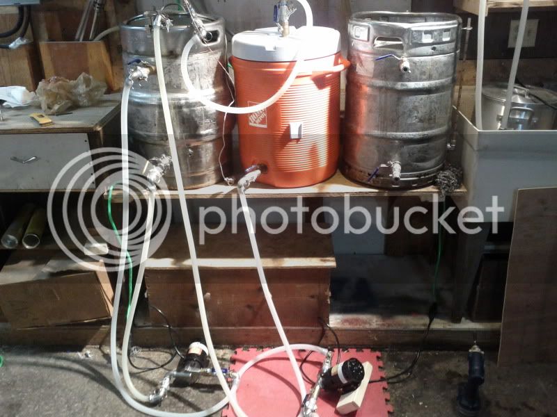
1. Need 2 or 3 more camlock connection hoses. I originally was planning on using one pump, but got a deal on the chuggers so I bought two. An extra 2 or 3 hoses will allow me to agitate HLT water via recirculation while the mash is also recirculating. Same goes for chilling/whirlpooling in the BK. I was amazed at how consistent the mash temperatures were, especially since I left the lid of the MLT cooler off the entire 60 minutes. But I had to manually stir the HLT water or else I would get stratification and the temps went down, or the PID was reading a cooler spot in the HLT and overshot my desired temps. I also need to get a different RTD for the HEX output reading. I bought two of the vessel mounted weldless probes, but they are some metric size threading, not ½ or 1/4" NPT” so it doesn’t screw into a tee connection mounted on the output of the HEX. I talked to Auber and they said they would replace the probe with a standard connection, I just have to ship it to them.

2. On the topic of mash recirculation, I need to figure out a better way to discharge the sweet liquor back into the MLT during recirculation, some sort of “recirc arm”. The camlock on the lid will work good, but with just the nipple on the inside it flows directly vertical into the grain bed. I counteracted this by sliding a silicone hose on the end of the nipple and laying in horizontally above the grainbed, but it kept wanting to move, and one time it actually fell out of the vessel spilling hot liquor all over the place. I need to divert the flow horizontally with a more permanent solution. I am thinking either a CPVC connection that is able to slide and is adjustable vertically or one of those adjustable snaplock tubes that Bobby M sells.

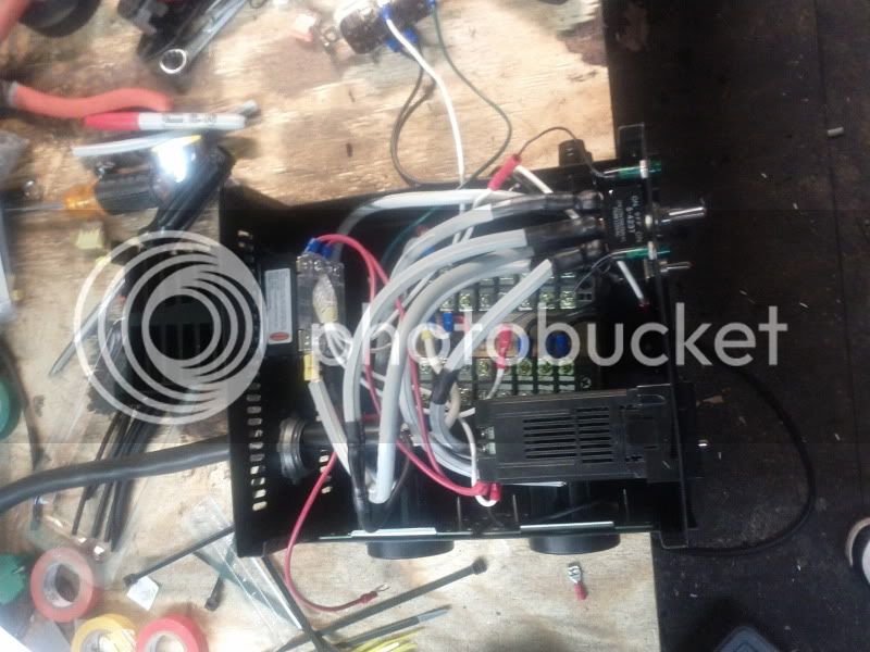
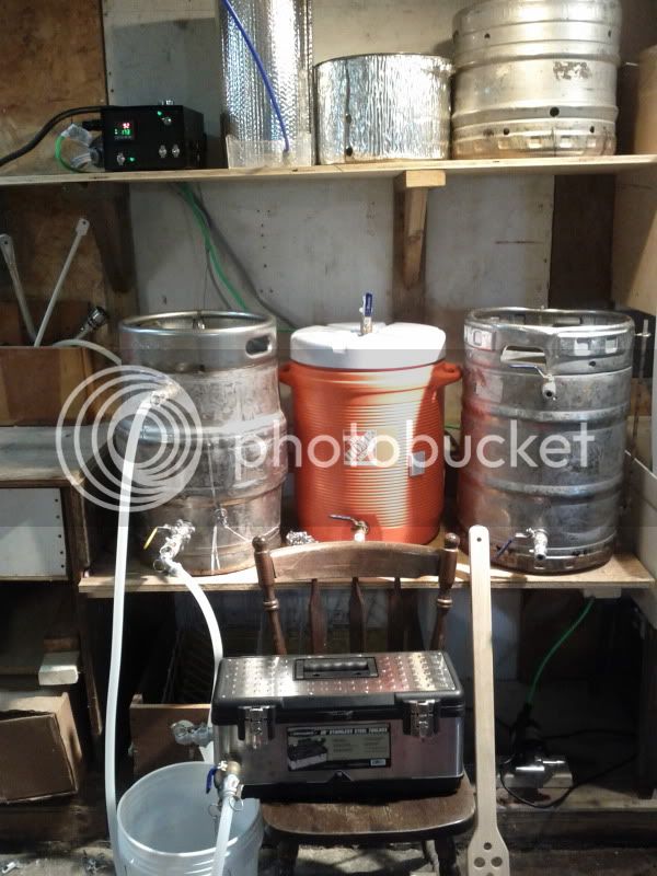
3. On the topic of pumps, I don’t think I am happy with the pumps in the toolbox. It gets in the way, is a bit cumbersome and the single pump was really hot even with the lid cracked open. It actually died out on me for about 10 minutes. It wouldn’t turn on and I thought I killed it, but it came on after sitting out for awhile. It will be even worse if I get the second one installed. I think I am going to permanently mount them to the underside of the brewstand instead. At the very least I will keep the one in the toolbox and hardmount the second, that way I can use the toolbox if I ever need the pump somewhere else.

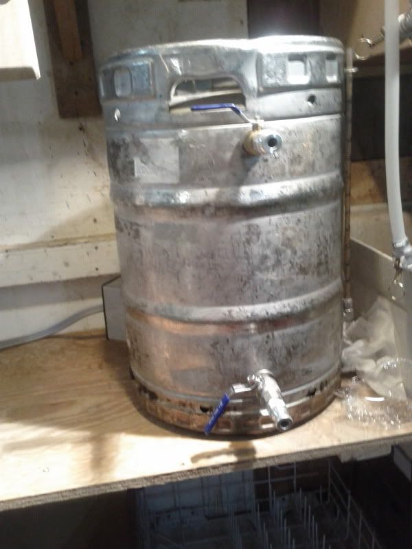
4. Need a whirlpool connection on the BK’s top valve – While recirculating the wort during chilling, it was just splashing back into the vessel. I am not a believer of Hot Side Aeration, but I don’t want to be a permanent tester of the theory either. Also, whirlpooling will help keep as much trub out of the fermenter as possible.

5. On the topic of trub in the fermenter - I need to adjust my pickup tube in BK to the side of the vessel – If I do the whirlpool I don’t want to be picking up in the center of the vessel like it is currently configured. I will probably just bend the copper to pickup as close to the side as possible.

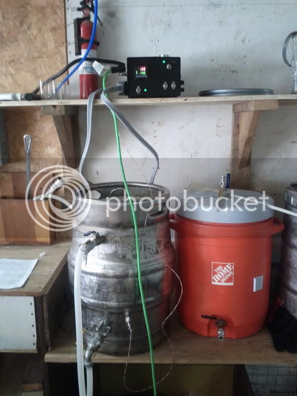
6. Need to install the sight glass in the HLT so that I can monitor volumes into the MLT. I was kind of running blind based on feel and ended up needing to add water to the BK the first batch, and had some extra sparge water in the second (leaving some sugar behind in the MLT). A sight glass calibrated to the nearest ½ or ¼ gallons will fix this.

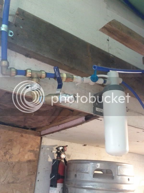
7. This one is probably just a dream, but I would really love to have a floor drain or at least a sink with a connection into the existing drain in the laundry room. I realize this would be a fairly big project, and it probably wont happen, but there is a ton of excess cleaning water that I have to temporarily store in a large (~50 gallon) Tupperware container due to my new clean in place process. I guess at the very least I could get some kind of a sump pump and hose that I can run into the laundry room on brew days. This weekend I was stuck filling buckets and carrying them to the laundry room sink. That is going to get old fast.

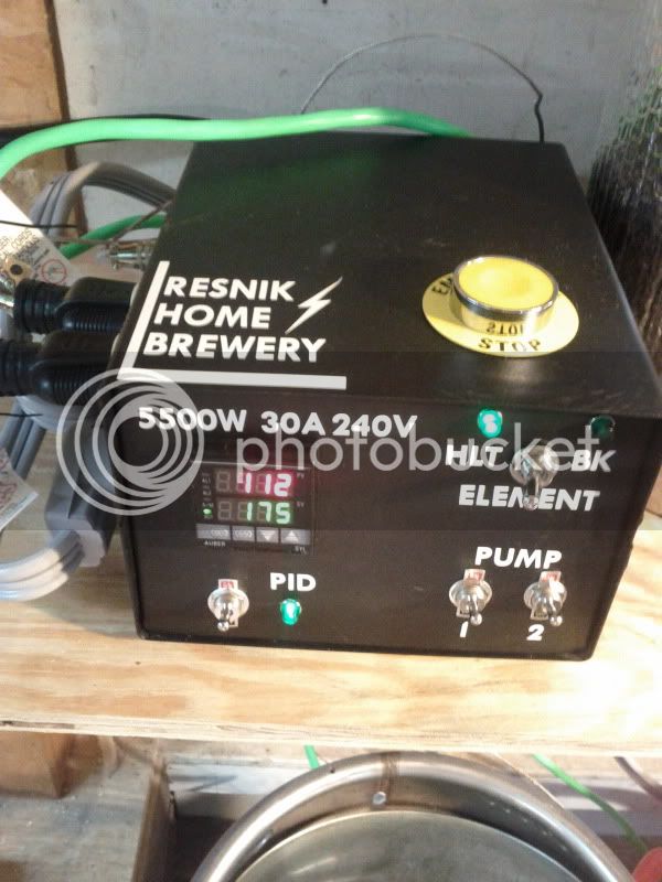
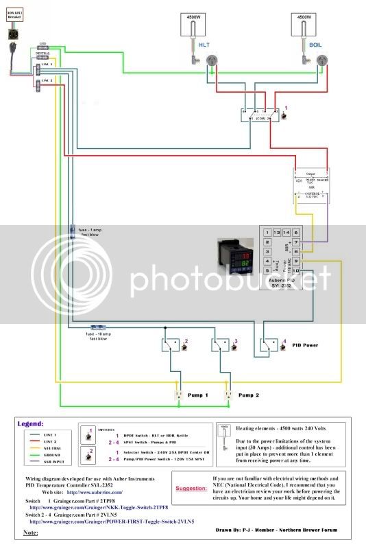
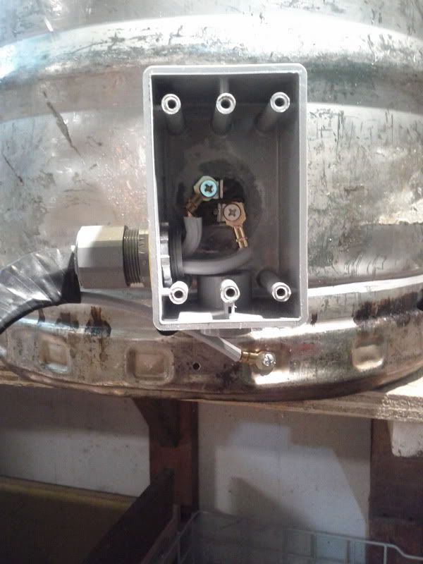
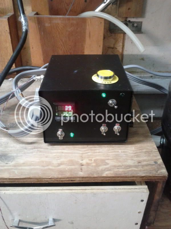
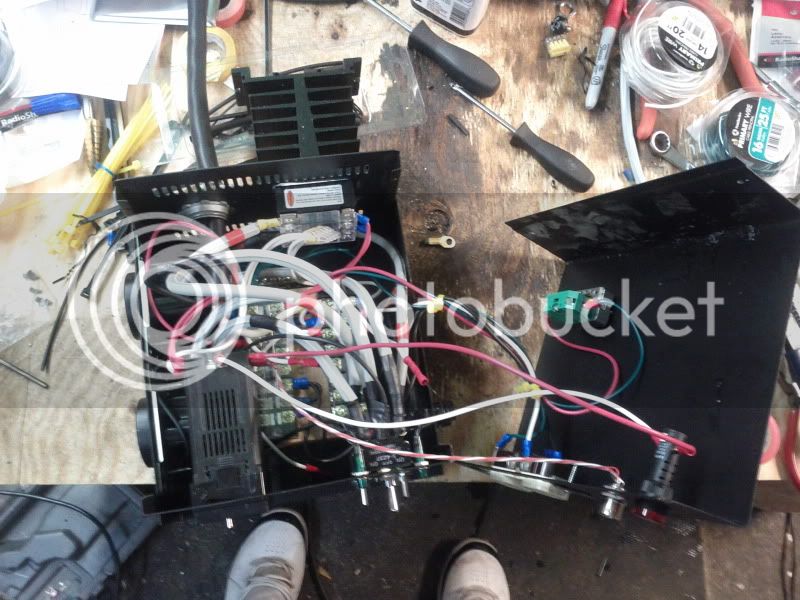
The electrical part of this system seems to be working great. One thing I would possibly like to have is an indicator light that shows when power is actually going to the elements. I feel like that might make it less likely to make a mistake and dry fire one of the elements. Right now all I have to go by is whether the DPDT switch is “ON” on either the HLT and BK, and then if the PID is showing an output in the bottom left corner of the display. Something like a router/modem status indicator is what I am thinking, but I may not even worry about it once I start to feel comfortable with the system. I guess the ideal approach would be to get some float valves installed that only allow power when the vessels have water in them, but I think that might be a bit expensive for the added security.

Sorry for the long rant, just wanted to get some of my complaints down in writing so I can come back to them later. I have already ordered additional camlocks from Proflowdynamics and the extra connections from Bargain Fittings (there goes another $100 bucks). Waiting on something else I need before I make the call on the mash recirc arm… hmm wonder if Bobby_M has refractometers in stock/on sale????
 
Okay, just pulled the trigger at Brew-Hardware (wow that took a lot of arm-twisting :drunk:). Picked up the “Mash Recirculation Return Tube”, a refractometer, decals for both sight glasses, and also custom decals for the control panel!

Heres what I ordered for the custom labels. I’m hoping this will cover everything (I added numbers to get up to 200 characters, figured I could use them to calibrate some buckets or carboys):

RESNIK HOME BREWERY 5500W 240V 30A ELEMENT HLT BK 240V 30A HLT BK PID PUMP 1 PUMP 2 PUMP 1 PUMP 2 PUMP 1 PUMP 2 TEMP SENSOR FUSE-10A FUSE-1A 1 2 3 4 5 6 1 2 3 4 5 6 1 2 3 4 5 6 7 1 2 3 4 5 6 7 8 9 10
 
You can get some small 120VAC indicator lights from radio shack if panel space is a problem. Just have to get hot from your element outlet or output of your element relays, then you won't have to deal with SSR leakage. You'll also need to grab the white neutral, unless you can just find a 240VAC indicator light, which I wasn't looking for at the time. I used a red and a green (couldn't find blue) for my DIY temp controller. Here's what they look like installed:
20120212_171957.jpg
 
Yep, thats what I am using on the panel already (in green), and is what I would use for the "element fire" lights.... probably in red.
 
Did some more work on the brewery this weekend:

Got most of the decals on the control panel, thanks to Bobby_M at Brewhardware for the sweet custom labels!
IMG_20120429_130638.jpg


Got the RTD installed on the output of the heat exchanger, and ran an autotune session with about 10 gallons of water in the HLT and ~4 gallons in the MLT. (I’ll do another autotune on the next brew session I think).

Temperatures in the MLT had about a 3 to 4 degrees lag behind the water in the HLT during the initial heating, but they evened out pretty quickly once the set temp of 175 was hit. I recirculated in the HLT to keep constant agitation, while also recirculating the ‘mash’ with the output valve half open.
IMG_20120429_130711.jpg


IMG_20120429_130659.jpg


Also did some work on my logo, I’d appreciate some feedback on this if anyone has any suggestions. I’m relearning GIMP since its been awhile since I used any graphics program other than Picasa and Paint.
BarredWindow-logo3-1.jpg


Other updates to the brewery:
- Installed stainless ½” NPT to ½” OD compression elbows in the BK and HLT in-port to use as a whirlpool/recirc agitators (thanks to my dad for bringing these fittings home from work, saved me about $50 bucks!)
- Took the pump out of the toolbox. I think I like having them mounted permanently under the brewstand better.
- Adjusted the BK’s diptube to pull more from the side of the kettle since I will now be whirlpooling. I just bent the copper tubing out towards the vessel wall with my hands/vise grips.
 
I know you used this wiring diagram from P-J to wire up your box. I was wondering where the indicator lights are hooked up, since I'm not seeing them on here.

Auberin-wiring1-a4-4500w-30c.jpg


Thanks!
 
Lets see if this works….first time trying to upload pics directly to HBT since I cant get on PB at work.

Indicator lights are easy, just connect one terminal to the ‘switched’ side of hot, and other to neutral. I used 110v lamps of course. Red is what I used for HLT, BK and PID indicators. You could also indicate when either pump is running, I have sketched that in green.

On a somewhat unrelated note, I’ve brewed 5 batches with this so far. On Sunday after my brewday was done I was going to clean the kettles with a hot oxyclean rinse through the entire system. I put about 5 gallons of water in the HLT and attempted to fire the element… no go. I was getting an “ORAL” error with blinking lights. I didn’t have time to fiddle with it, but I think I may have pulled a wire loose on the RTD. At least I hope that’s all it is, I’ll check it out tonight.

Auberin-wiring1-a4-4500w-30c_INDICATORS.jpg
 
Thanks!

Did you ever figure out what went wrong with the element?

Any chance you have a parts list of everything you needed to make this? This is the exact setup i'm shooting for. Also...what gauge wires are needed for all the internal connections. I haven't seen any of these details on any of the diagrams from P-J.
 
I don’t have a detailed parts list, but I can try to help you along the way as much as possible. Do you have a build thread started or are you just planning now? This guy has a detailed list that I used as a start point for my build, it would be a good read:

https://www.homebrewtalk.com/f170/e-herms-build-4500w-elements-pics-310259/

Havent had time to figure out what’s up with the element, but I am almost certain that it is the RTD wire, since that error is common when the probe is not plugged in. I was moving my HERMS coil around all over the place after the brew day and I don’t remember unplugging the RTD probe. I need to get some better wire sheathing for it.

Interior wiring in the control panel is all either 8 awg or 14 awg. 8 awg for all feeds that see high current (main feeds from SPA panel, element outlets, SSR output), and 14 awg for all others.

I would suggest you start a thread if you haven’t already and post exactly what it is you want to do. It’s a good chance that P-J or someone else has a diagram already drawn up.
 
On your HLT/BK switch, does it have a center setting that will cut power from both elements without turning off the PID? Not sure if this would be necessary or not, but might be useful. Are there switches that are made like that?

I'm not ready to build right now, but I'm looking to get all my plans together. I've been doing all grain for awhile now with a cooler mash tun...batch sparging and boiling on propane burner. I'm looking to go 2 kettles, one for hlt and one for bk, and probably use the cooler setup at first and eventually switch to a third kettle for the mlt.

Your setup looks like what I would be looking or, except i would like a second pid for the mash tun to keep track of the mash temp. How do you keep track of your mash temps?

What are your thoughts on having a switch to control power to the entire box? Would this be a useful feature to have?
 
On your HLT/BK switch, does it have a center setting that will cut power from both elements without turning off the PID? Not sure if this would be necessary or not, but might be useful. Are there switches that are made like that?

Yes, it is a DPDT – center position off switch. This ensure that I can have the PID on without firing either element, and only one can be fired at a time. Heres a link: http://www.grainger.com/Grainger/NKK-Toggle-Switch-2TPC5

I'm not ready to build right now, but I'm looking to get all my plans together. I've been doing all grain for awhile now with a cooler mash tun...batch sparging and boiling on propane burner. I'm looking to go 2 kettles, one for hlt and one for bk, and probably use the cooler setup at first and eventually switch to a third kettle for the mlt.

I’m pretty much at your second step, and am on the lookout for a third keggle that I can use as an MLT. The extra 5 gallons of capacity will be much appreciated!

Your setup looks like what I would be looking or, except i would like a second pid for the mash tun to keep track of the mash temp. How do you keep track of your mash temps?

I use a HERMs coil in the HLT to recirculate the mash liquor through, with the RTD probe attached to the output of the coil with a 1/2” stainless tee fitting. My process starts by filling HLT almost completely full and get the whole thing up to strike temps. Mash in and let the MLT settle for about 10-20 minutes. While this is going on, add additional water to the HLT if needed and get that back up to desired mash temp (This is usually quick since desired temp is 150-155 usually, and I strike in at around 170 depending on grain quantity and temps). Once the HLT temp is stabilized, start the recirc through the HERMs coil (This is where having the cooler is an advantage because I don’t necessarily have to start the recirc right away, the cooler will hold temps well for at least 45 minutes). Towards the end of the rest, set the PID to mash out (165-170) temp and recirc for an additional 10-15 minutes or so. Then drain 1st runnnings, and sparge from HLT (water is already at 165-170). Switch the element over to the BK once the element is submerged with liquor.

What are your thoughts on having a switch to control power to the entire box? Would this be a useful feature to have?

IMHO, its unnecessary in my setup. I have a switch to the PID, which if turned off should kill the elements from firing (note there still may be hot wire running to the element the way that the SSRs work). If I need to completely kill the whole circuit I will either push the e-stop button, flip the switch at the SPA Panel (which is within arms reach of the brewstand), or unplug the whole thing. An extra power switch would just be an added expense in my opinion.
 
Back
Top