ebay aquarium temp controller build

Homebrew Talk - Beer, Wine, Mead, & Cider Brewing Discussion Forum

Help Support Homebrew Talk - Beer, Wine, Mead, & Cider Brewing Discussion Forum:

This site may earn a commission from merchant affiliate links, including eBay, Amazon, and others.
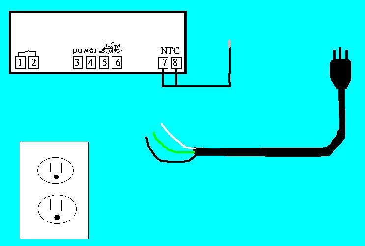
I wired up the controller with a cord off an old cable box, but no power.
I used an old wall wart, no power.

are you feeding it 120V?

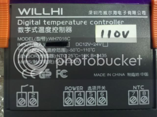
It says it's the correct one- '110VAC, 50Hz/60Hz' marks below the power screws.
Not getting anything.


Slow down a second, Ben.

I don't know what your "old cable box" cord was, but in your first post, you said you used a old wall wart, which is NOT going to work. That's DC power and not AC, which is why Bjorn asked if you were feeding it 120VAC.

Your other response only confirmed that it was a 120VAC controller, but not whether you were feeding it 120VAC for power.

And if you did in fact feed it 12VDC you may have fried the controller...
 
And if you did in fact feed it 12VDC you may have fried the controller...

I would think it would be highly unlikely, the contorller side is most likely 5-12V dc anyway, the 120V ac would go through a small stepdown transformer, to a bridge rectifyer to a voltage regulator (maybe, but probably). Feeding it with 12V dc would probably just heat up the transformer a bit. (disclaimer, I am no way an expert in electronics but do have some basic knowledge. Anyone else done Electrical Engineering 101?)
 
Thanks, guys.
I understand what you're saying and I got it going.
:ban:

The wart does have a transformer which made it inappropriate for the application.
I had just gotten a bit frustrated after having no luck with the initial 'straight' power cord...and I had not hooked up the sensor or held down the power button long enough, apparently...which I now see is necessary.


It works and I appreciate the assistance.:mug:
 
Glad you got it working Ben.

I would think it would be highly unlikely, the contorller side is most likely 5-12V dc anyway, the 120V ac would go through a small stepdown transformer, to a bridge rectifyer to a voltage regulator (maybe, but probably). Feeding it with 12V dc would probably just heat up the transformer a bit. (disclaimer, I am no way an expert in electronics but do have some basic knowledge. Anyone else done Electrical Engineering 101?)
Yeah....no, not even close ;) There's no transformer in that little thing...it would be a solid state buck power supply. No harm would be done at all feeding it 12VDC. :mug:
 
Glad you got it working Ben.


Yeah....no, not even close ;) There's no transformer in that little thing...it would be a solid state buck power supply. No harm would be done at all feeding it 12VDC. :mug:

Oh... ok, yeah I didn't think any damage would be done to something designed for 120 V if feed with 12 V. How much would one of those buck supplies cost? and do you still need to rectify the ac first or does the chip do that too?
 
Oh... ok, yeah I didn't think any damage would be done to something designed for 120 V if feed with 12 V. How much would one of those buck supplies cost?

I wasn't concerned about the voltage but rather the current, DC vs AC. Not that I'm an EE or anything, just thought that it could have possibly damaged the unit in some way.
 
I wasn't concerned about the voltage but rather the current, DC vs AC. Not that I'm an EE or anything, just thought that it could have possibly damaged the unit in some way.

Yeah, the way I look at it though is ac is design for the electrons going both ways so feeding it with dc the elctrons only go one way and most likely the thing won't work but probably won't break either. Feeding dc equipment with ac however forces electrons round the wrong way in the circuit leading to problems. I'm no EE either but thats just how I look at it in my mind.
 
Yeah, the way I look at it though is ac is design for the electrons going both ways so feeding it with dc the elctrons only go one way and most likely the thing won't work but probably won't break either. Feeding dc equipment with ac however forces electrons round the wrong way in the circuit leading to problems. I'm no EE either but thats just how I look at it in my mind.

Darn you and your logic!!! :mug:
 
so I got my temp controller today its not the original one in the thread and was just looking for an easy wiring diagram. it didn't come with anything indicating how it needs to be wired up.

now this is going on my keezer so I am not controlling heating and cooling.

IMG_20101216_090204.jpg


from what I can tell

1 and 2 are switched and my outlet needs to be connected to that

3 and 4 are power so thats from my extension cord

5 and 6 I have no idea what the Chinese letters mean

7 and 8 are where the temp probe is already plugged in.

here is what I have to work with can some one finish the diagram for me please?
xE1ra.jpg


-=Jason=-
 
so I got my temp controller today its not the original one in the thread and was just looking for an easy wiring diagram. it didn't come with anything indicating how it needs to be wired up.

now this is going on my keezer so I am not controlling heating and cooling.
from what I can tell

1 and 2 are switched and my outlet needs to be connected to that

3 and 4 are power so thats from my extension cord

5 and 6 I have no idea what the Chinese letters mean

7 and 8 are where the temp probe is already plugged in.

here is what I have to work with can some one finish the diagram for me please?

-=Jason=-

listen to Bjornbrewer
 
No, that's not going to work...you're not getting power to the receptacle.

I don't feel like drawing this: jump the black wire from pin 3 to pin 1. go from pin 2 to the hot of the receptacle. connect the neutrals from the receptacle and controller (pin 4).

just FYI, the controller doesnt take power in, and then output it to the device to be controlled...it just closes a contact. That contact opens and closes the circuit to suply power to the device to be controlled.
 
Bjornbrewer, thank you very easy to understand. I shouldn't have any problems now.

hardest part of this is going to be programing the thing.

-=Jason=-
 
well I borrowed a garbage disposable cable from work and tested out my unit and it did power on and when I grabbed the probe the temp started to rise, now to get into the setting menu and figure out what it all means.

-=Jason=-
 
Seriously, I'm not usually the weakest link, but damn...

So, I had wired up the controller as shown in the first diagram, from first page.

Came on no problem ...then after about 5 minutes it tripped the house breaker.

Unplugged, reset breaker, plug back in...no power.

Unwire everything except power and probe...comes back up...so, wired incorrectly.

Two questions...1. on the diagram, is the green incoming line from the power cord wired into the outlet or to the ground screw?

2.Is the wire from controller input #2 tied together with the incoming-in my case 'white'- power cord wire and attached to the heating post?

On page 51, there is a pic of a nice wiring setup that appears quite different from this one and I can almost make all the connections out, but not quite.
What is the advantage of the wiring strip?

possibleschematic.jpg


12062010061.jpg
 
Two questions...1. on the diagram, is the green incoming line from the power cord wired into the outlet or to the ground screw?
The ground from the line cord goes to the ground screw on the receptacle.

2.Is the wire from controller input #2 tied together with the incoming-in my case 'white'- power cord wire and attached to the heating post?
yes...all the whites (neutrals) should be tied together.

On page 51, there is a pic of a nice wiring setup that appears quite different from this one and I can almost make all the connections out, but not quite.
What is the advantage of the wiring strip?
it takes the place of wire nuts. I don't see any other reason for it...cant make out all the connections either.


Did you break off the tab on the hot side of the receptacle to make the two independently controlled?
Being that the breaker tripped after 5 minutes tells me you have it overloaded, not shorted. What are you controlling with this thing and what else is on that breaker?
 
This is sweet! I am going to use one of these to build a chocolate tempering machine, running 2x100W light bulbs to heat the bowl
 
after getting my unit I have realized that my box from Radio Shack is MUCH larger than I need, I wonder if I can take it back with out receipt and exchange for a smaller box

-=Jason=-
 
Bjorn, thanks for all the info.
The tabs are broken and the unit was plugged into a high use area outlet, although I had not yet plugged anything into the unit's outlets. Lower load outlet next time.

Going to wrap up a couple presents for SWMBO and then get back to the controller.
Thanks again for taking the time to help, it's truly appreciated.
 
Are you plugging the fridge into the outlet from this controller? And are you modifying the refridgerator in any way?
 
Chocolate tempering? Not sure what that is (is that fancy for "melting"?), but I like the creativity! :mug:

Yeah its keeping the chocolate at a low temp (82-90 degrees F) melted, but low enough to keep crystaline structures formed in the right chain. Makes chocolate shiny and hard.

Its what they use to dip truffles and make other chocolates.
 
Are you plugging the fridge into the outlet from this controller? And are you modifying the refridgerator in any way?

Yes. no. You can just plug the fridge in and away you go...instead of the internal t-stat controlling the temp, you're essentially plugging and unplugging the fridge via the controller.
 
I just built two of these and they work great!

Where are you guys putting the probe? Is it water proof?

Cheers
 
I just built two of these and they work great!

Where are you guys putting the probe? Is it water proof?

Cheers

I taped the probe on my carboy - covered with some bubble wrap. My fermometer is reading between 62 and 64 Farenheit and the temp controller is showing 17.2 celsius (63 F) so I'd say it is right on!
 
This high falutin' decade old Walgreen's heating pad has an auto off feature and keeps cutting off before bringing the filled carboy to it's target temp.

I assume there are heating pads without an auto off I could buy, just was hoping to make this as scavenger/low cost as possible a project.

What type of heating elements are you guys using?
If a light bulb, where and how is it placed in the fermenting chamber?

Adding a couple pics...just because:mug:

DSC00832.jpg


DSC00833.jpg


DSC00834.jpg


DSC00836.jpg


DSC00829.jpg
 
with the reptile heater bulbs or maybe something wired to the inside of the fridge/fermenter like this?...

Ceramic-Lamp-Socket-Porcelain-Lamp-Socket-E26-E27-Lamp-Socket.jpg
 
Another option which I am using is to put this small heater into the fridge wired into the heating side of the controller. Since I have my controller mounted into the door of my fermentation fridge I just ran the heating wires down to an outlet box that I plug this heater into and it works perfectly to maintain the temperature, plus this thing is only 200 watts so you don't have to worry about drawing too much power or getting too hot in the fridge.
 
Last edited by a moderator:
but the problem seems to be that when the unit reaches the target temp and power cuts off, it resets to off...so that when it gets power again it's at the 'ready' state but not actually on.

DSC00837.jpg


DSC00838.jpg
 
Sounds like you need a different heater, or you need to take this one apart to hardwire the power.
 
Another question is do you have the temperature set to the maximum so that when it is powered it will always turn on (this is how I have it set)?
 
No matter what setting it's on, if it loses power, when it comes back on it is at the ready but not in whatever setting it was on when it lost power. It's a handy little heater, so I think I'll use it around the house and go with the ceramic reptile bulb method.

I made a little fan box out of an old computer power supply to move the air around, but where should the bulb be located?
Since heat rises, I assume at the bottom?
I would probably need to replace the plastic shelf with some unlikely to melt.
 
In that small of a space it doesn't really matter where you mount the bulb. I used to have a similar setup with a ceramic bulb mounted near the top and a computer fan to circulate the air. Actually I had 2 bulbs just because I got 2 for the price of one, but that was probably over kill. Keeping temp in the fridge all winter long was not a problem.
 
Back
Top