Austinjs0102
Active Member
if only i was this smart lol. This is simply amazing. Not only is all the hardware amazing but the fact your are programming it all and making it look so clean.

if only i was this smart lol. This is simply amazing. Not only is all the hardware amazing but the fact your are programming it all and making it look so clean.


Are you by chance an electrical/software/hardware engineer as well as master brewer haha?
Love this thread, i check it daily to see the progress.


very cool. what size control panel are you using?
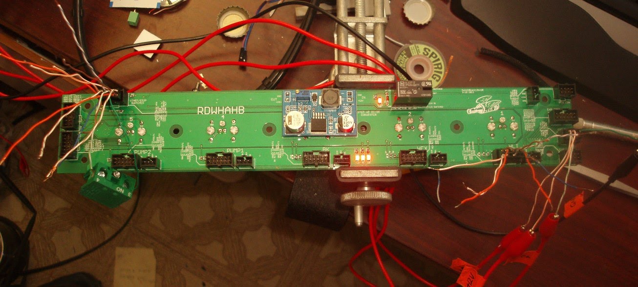

The LCD key/switch breakout panel is working like a champ during my bench testing. This board breaks out 5 ports for the HLT, MLT, BK, Pump 1, and Pump 2 LCD keys. It also provides connections for the switches and dials for those same items. A 12VDC to 24VDC step up converter (blue board) provides power to turn the contactor on in the power control box. This 24V output is controlled by the black relay to the right which requires the following to be turned on:
1. All element/pump control switches are in Off position to initially energize (my safe start feature)
2. The emergency stop is not activated.
The red LED next to the relay shows that it is on. I tested both the conditions above and it works perfectly. The three other red LEDs at the bottom middle of the board indicate that it has proper +3.3V, +5V, and +12VDC supplies.
Next I have to make cables to connect between this board and the other 4 LCD keys and then wire up the switches and dials.

Quick update. The LCD keys are fully functional using a native control GUI, I will be working to implement a control program in my own code soon.
The camera has a hard time seeing the text in each switch, oh well.
Wiring up the switches and dials are next.

 SICK build!!!
 :rockin:
Um. Your "breakout" board. Is that custom screened? Or an off the shelf product?
It's not every day I see a circuit board with "RDWHAHB" on it. That is so awesome I might wet myself.
") Thanks for the reply. Happy brewin' to ya!
Thanks for the reply. Happy brewin' to ya!Just found this thread and all i can say is fricken awesome! Nice work, when its all done you should post a video brewing a batch with it. very nice cheers!
.Have you thaught of using a plc to control this masterpiece or are you happy with your processor interface? I know labview interfaces with plc's nicely. .
Hey had a question about your digital temp sensors..
i bought the same ones, and im looking to hook them up to a NI myDAQ (http://www.studica.com/ca/en/National-Instruments-students-ni-labview-mydaq/ni-mydaq/781327-01.html) and using its digital in's
and finally using labview to provide an analog input for an SSR.
Im treading new ground with this. Not an electrical guy, this is for a mechatronics class. Do you see any pitfalls? Should i go analog with the sensors? (thermistors). I beleive I would need a wheatstone bridge to then convert the resistance to voltage.
Very nice. I've seen a LOT of brewery builds, and this one has to be at the top of the list. Not only are you using a very advanced system of controls, you're one of a very few who have used peristaltic pumps. Great work


The stepper motor noise is a bit annoying but overall I am pleased with the end result.
Half-step it. Hell, 16th step it. you'll quiet it down a fair bit.


Just wondering FB, do you have a way of automating your strike volume, if your hlt is not being filled by the pumps the tachs on the steppers won't be able to estimate this for you
runs4beer said:Not FB but I have contemplated the use of digital scales under the all 3 vessels to calculate liquid volumes. Would this type of input work with Lab View (I believe that's the platform you're using)? If so I would think it would be very precise way to set strike volumes, track boil off rates and fine tune the sparge. Thoughts?
Enter your email address to join:
