
The Pol
Well-Known Member
- Joined
- Feb 12, 2007
- Messages
- 11,390
- Reaction score
- 117
WARNING, WARNING!!!!!!
DANGER, DANGER!!!!!
Electricity KILLS! I am not an electrician, nor do I claim to have any working knowlege of electricity and its properties!!!! Build this panel at your own risk!!!
This thread will document the conversion of my existing HERMS to ALL electric complete with PID, SSR, control panel etc.
I have already installed a new circuit in my garage using a DP 30A GFCI, #10 AWG wire to a (4) prong outlet, this will supply sufficient power to my MASH and to my BOIL halves of my control panel. It will require 13A during mashing, it will require 23A during the boil.
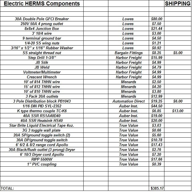
Here is a complete parts list. The remainder of this thread will document the entire build in separate phases. (this may be revised as the build requires)
PHASE #1. I will be converting my keggle to electric. Stay tuned for the pics, commentary and instructions to come.
DRILL A 1.25" HOLE THROUGH THE SIDE OF THE KEG AT THE 2.5 GALLON POSITION ON THE KEG
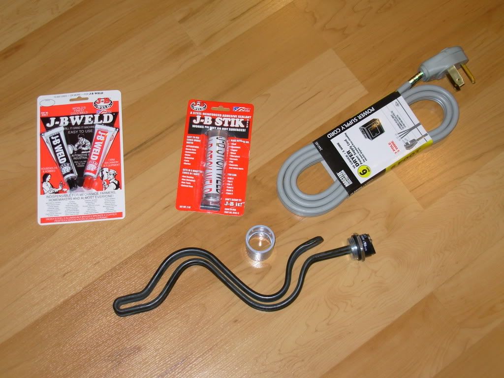
To build the element you will need:
5500W RIPP element
JB Stik
JB Weld
1" NON conductive PVC slip coupling
6' 10/3 dryer cord
(2) wire end terminals
Wire cutters
Philips screw driver
#1. Separate the three wires so that they are not attched approximately 2" from the terminal ends. (this will allow you to separate the ground wire and attach it to the keg if you place your thermowell in the same position that I placed mine)
#2. Cut approx. 1.5" from the end of the two HOT wires, yes this will remove the factory terminals.(this will allow the ground wire to reach the side of the keg with the element installed)
#3. Attach (2) new terminal ends to the two HOT wires on the cord.
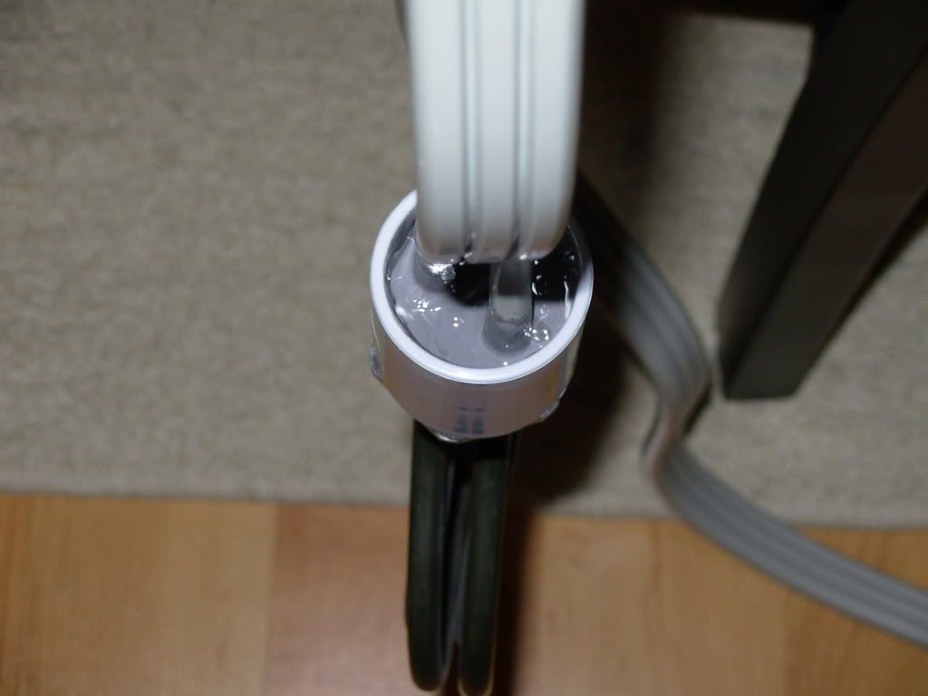
#4. Slide the PVC coupler over the end of the cord
#5. Attach the two HOT wires to the element. Be sure to leave GROUND wire OUTSIDE of the coupler, this will attach to the keg.
#6. Knead a small ammount of JB Stik and roll it into a thin rope. Wrap the epoxy putty around the base of the element, where the PVC coupler will be seated. Press PVC coupling into place. Let set for 20 minutes.
#7. Mix two full tubes of JB Weld epoxy well and pour it into the void where the electrical connections lie. This will fill the void sufficiently to pot the connections and wires.
#8 Hang the element from the cord for 24 hours to allow proper curing of the epoxy.
PHASE #2. I will be building a control panel to run all of the components of this system, pump, BK boiler and HLT heater and mixer. PANEL NEARLY COMPLETE, PICS AND INSTRUCTIONS WILL BE POSTED BY JANUARY 1ST!!
DANGER, DANGER!!!!!
Electricity KILLS! I am not an electrician, nor do I claim to have any working knowlege of electricity and its properties!!!! Build this panel at your own risk!!!
This thread will document the conversion of my existing HERMS to ALL electric complete with PID, SSR, control panel etc.
I have already installed a new circuit in my garage using a DP 30A GFCI, #10 AWG wire to a (4) prong outlet, this will supply sufficient power to my MASH and to my BOIL halves of my control panel. It will require 13A during mashing, it will require 23A during the boil.
Here is a complete parts list. The remainder of this thread will document the entire build in separate phases. (this may be revised as the build requires)
PHASE #1. I will be converting my keggle to electric. Stay tuned for the pics, commentary and instructions to come.
DRILL A 1.25" HOLE THROUGH THE SIDE OF THE KEG AT THE 2.5 GALLON POSITION ON THE KEG
To build the element you will need:
5500W RIPP element
JB Stik
JB Weld
1" NON conductive PVC slip coupling
6' 10/3 dryer cord
(2) wire end terminals
Wire cutters
Philips screw driver
#1. Separate the three wires so that they are not attched approximately 2" from the terminal ends. (this will allow you to separate the ground wire and attach it to the keg if you place your thermowell in the same position that I placed mine)
#2. Cut approx. 1.5" from the end of the two HOT wires, yes this will remove the factory terminals.(this will allow the ground wire to reach the side of the keg with the element installed)
#3. Attach (2) new terminal ends to the two HOT wires on the cord.
#4. Slide the PVC coupler over the end of the cord
#5. Attach the two HOT wires to the element. Be sure to leave GROUND wire OUTSIDE of the coupler, this will attach to the keg.
#6. Knead a small ammount of JB Stik and roll it into a thin rope. Wrap the epoxy putty around the base of the element, where the PVC coupler will be seated. Press PVC coupling into place. Let set for 20 minutes.
#7. Mix two full tubes of JB Weld epoxy well and pour it into the void where the electrical connections lie. This will fill the void sufficiently to pot the connections and wires.
#8 Hang the element from the cord for 24 hours to allow proper curing of the epoxy.
PHASE #2. I will be building a control panel to run all of the components of this system, pump, BK boiler and HLT heater and mixer. PANEL NEARLY COMPLETE, PICS AND INSTRUCTIONS WILL BE POSTED BY JANUARY 1ST!!


 . As he had to wire elevators, he was a bit fussy.