EBay fish tank controller build using Wal-mart parts

Homebrew Talk - Beer, Wine, Mead, & Cider Brewing Discussion Forum

Help Support Homebrew Talk - Beer, Wine, Mead, & Cider Brewing Discussion Forum:

This site may earn a commission from merchant affiliate links, including eBay, Amazon, and others.
EPIC FAIL! So I just used this for the first time yesterday. I had set the outlets up to run both for heating and cooling. Bad idea.

I had a belgian wit in my 60F craw space with a brew belt attached. Unfortunately the brew belt could not get up to my desired 72F. So, I added a heating pad underneath and the temps started going up. Great!

My wife and I then went out for the evening. When we got home I forgot to check in on the fermenter until 7 this AM. When I checked it the temp was over 82F! Evidently, when the temp hit the desired temp, the fermenter kept warming up. The temp controller then kicked into cooling mode and kicked the warmers back on an up she went.

Lesson: Have dedicated outlets for heating and cooling. I haven't given it a taste yet but I suspect I have a banana beer.
 
I put this setup in my fermentation chamber today. It's a mini fridge with a small 200 watt personal heater. I went with 16 gauge wire because the heater is rated at 2 amps. The heater is a Lasko My Heat Personal heater I got at WalMart for $11. I filled my fermentation bucket up with 5 gallons of water and put it in the chamber to test everything out, and so far the temp is holding at 63-65 degrees. It's in my garage and the temp in there was about 55 degrees today and it's a little colder tonight. I think this is gonna work out great.
 
Lesson: Have dedicated outlets for heating and cooling. I haven't given it a taste yet but I suspect I have a banana beer.

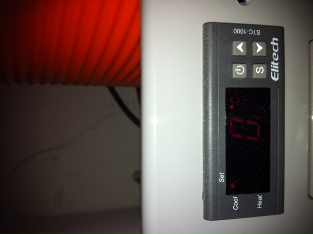
Review this picture from the original write-up:

2hgrzvt.jpg


MC
 
I just wired this up and am getting both outlets with power when the heat is on and both work when the cool is on. Can someone please help???
 
What voltage does the wiring diagram say? That will tell you if you have the 120V or the 240V

I have seen some say 220 and they are the correct one. I believe mine does but it is a STC1000 so it should be the correct one.
 
That's the STC-1000. That's the right one.

MC

Any idea why it wont stay even remotely close to the set temp? Ive used it on 2 different refrigerators, I cant seem to get it to work properly. I have gotten some advice but none of it has really led me in the right direction.
 
Any idea why it wont stay even remotely close to the set temp? Ive used it on 2 different refrigerators, I cant seem to get it to work properly. I have gotten some advice but none of it has really led me in the right direction.

Based on your posts in other threads I'd say you have the 220v controller. You can check to see what voltage it was built for by taking the case off and looking at the transformer. What voltage is the unit plugged into?
 
I have seen some say 220 and they are the correct one. I believe mine does but it is a STC1000 so it should be the correct one.

If that wiring diagram states 220V input, then it is PROBABLY a 220V controller.
There is a guy on here that figured out how to change the transformers out on these things... may look it up.
 
Hmmm, a number of auctions on ebay read:

Power Supply: 220 ~ 240V AC ± 10% or 100 ~ 120 V AC, 50 / 60 Hz
 
JonesCreek said:
Hmmm, a number of auctions on ebay read:

Power Supply: 220 ~ 240V AC ± 10% or 100 ~ 120 V AC, 50 / 60 Hz

It's two different models. Most of the sellers send the voltage of the country it's being shipped to, but some require that you request which one you want, and some screw up and send the wrong one occasionally.
 
Based on your posts in other threads I'd say you have the 220v controller.

If a 220VAC model were used on a 110VAC circuit, you would think that the display itself would either not light up at all, be very dim or have random displays... but that was not mentioned his other thread.

BraxtonBrewery, did you test the controller with, say, a lamp instead of a fridge (on the cooling output)? I would set F1 cooling temp to roughly a couple of degrees above room temperature then heat the probe with a hairdryer to see if the lamp comes on (and whether the lamp is at the usual brightness).

Once the lamp comes on, use an ice cube or cold water to quickly cool the prob to verify that the lamp turns off F2 degrees below F1. Then quickly reheat the probe again to verify that the fridge won't be turned before the F3 (compressor delay value of the default 3 minutes).

(Don't forget to reset F1 to desired fridge temp and turn fridge's internal setting to high.) If the lamp tests work but the fridges fail, I would verify that the compressor isn't overheating (from begin turned on too frequently).
 
If a 220VAC model were used on a 110VAC circuit, you would think that the display itself would either not light up at all, be very dim or have random displays... but that was not mentioned his other thread.

Actually the 220V model's display will work, but the relays won't activate.

To the guy with the problem, test the unit with a lamp, a cell phone charger with an LED, etc.

MC
 
I started to wire mine up last night but ran into a snag. The wire clamps on the heating and cooling circuits are fixed closed. It almost seems like they weren't made correctly or got solder in them during assembly. I have emailed the seller, and got a response requesting photos. I am waiting to hear back from them before I tear into it and desolder those terminals.
 
I started to wire mine up last night but ran into a snag. The wire clamps on the heating and cooling circuits are fixed closed. It almost seems like they weren't made correctly or got solder in them during assembly. I have emailed the seller, and got a response requesting photos. I am waiting to hear back from them before I tear into it and desolder those terminals.

That's strange. Mine were tight and required some torque but I got them loose with a small-medium flat screwdriver.

MC
 
Misplaced_Canuck said:
That's strange. Mine were tight and required some torque but I got them loose with a small-medium flat screwdriver.

MC

The screws feel like they are turning. Maybe I need to look a little closer and make sure I have my driver in the notch. (Diesel mechanic prepares to swallow pride after returning home)
 
The screws feel like they are turning. Maybe I need to look a little closer and make sure I have my driver in the notch. (Diesel mechanic prepares to swallow pride after returning home)

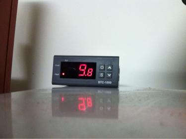
The screws don't come out. The little gate will lift up though, and reveal a small hole in which you put the wire in.

MC
 
Misplaced_Canuck said:
The screws don't come out. The little gate will lift up though, and reveal a small hole in which you put the wire in.

MC

Yeah. Power and sensor are fine. Heat and cool appear to be stuck.
 
image-4203960826.jpg

Just got it all figured out! Thanks for the guidance of my first electrical build. Should be able to complete the next one in about 15 minutes start to finish.
 
I got mine together too. Didn't build a box though. I wired to cooling circuit directly into the fridge in place of the thermostat. The only thing left is to find a heater and a permanent home on the outside of the fridge for the controller. Waiting for her to come up to 13C.

image-3788905828.jpg


image-3966321310.jpg
 
BraxtonBrewery, as mentioned a few posts ago...also check that you've broken the metal tab between the two outlets from Photo 3 in Post 3. (Use pliers to bend the metal back and forth to sever the connection.)

Otherwise, your fridge will be turned on when EITHER cooling OR heating is required. The fridge will turn on when the temp reaches 1c above your target temp. But when the temp reaches 1c below your target (i.e. when it's already cold enough), the heat function will activate but with tab unbroken, the heat relay is also connected to your fridge.

Eventually, your fridge will overheat and won't bother turning on when it needs to - giving you random results. (The ice cube lamp test will leave your lamp ON even when it's BELOW your target temp.)
 
Just put this together using the instructions in the first post. Used a cigar box for the case. Everything worked on the first try. Thanks for all the help in this thread!
 
Anyone know the wiring schematic for the single stage controller? The poles on the back have both "loading" and "power supply" terminals.

I want to make this as easy and cost effective as possible, so I am just going to take out the thermostat in the fridge and wire the temp controller into the line. There are black and white wires going into the thermostat, so I figure it should be fine?

Has anyone done this? Thanks.

I have one of them controlling my keezer and two in my HERMS control panel. Most of the sellers of these have changed the labeling on the terminals since I drew this, but you should still be able to figure it out. The one labeled "loading" should be the switch, and the one labeled "function" or "lock" can be ignored. FWIW, depending on the fridge wiring, it may be easier to create an external box that the fridge plugs into rather than trying to integrate it.

5712-single-stage-wiring.jpg

Thanks for the diagram! I had a good idea of how it should be wired, but it's been a while since I worked with electricity.

The thermostat of my fridge has a black and white line. I'm guessing it is 110V AC, but I'll test it with my multimeter when I get a chance. If that's the case, it would just be a simple matter of swapping the temp controller for the thermostat, plugging the black line into power supply 1 and the white line into power supply 2 and that's the end of it. Correct? The temperature controller housing can operate in temps down to 32 degrees, so I figure it won't be an issue to keep it all inside.
 
Thanks for the diagram! I had a good idea of how it should be wired, but it's been a while since I worked with electricity.

The thermostat of my fridge has a black and white line. I'm guessing it is 110V AC, but I'll test it with my multimeter when I get a chance. If that's the case, it would just be a simple matter of swapping the temp controller for the thermostat, plugging the black line into power supply 1 and the white line into power supply 2 and that's the end of it. Correct?

Doubtful. The two wires are likely the legs of a switch, not a hot and a neutral. You'd want to wire the outgoing leg to one of the switch terminals on the controller, and the incoming would get split and wired to the other switch terminal and one side of the power terminal. You'd still need to run a neutral from the incoming power on the fridge to the other side of the power terminal on the controller. This is all assuming the thermostat is switching the full 110V.

If you want to wire it into the fridge, it's likely going to be easier to just leave the thermostat alone, and wire the controller into the incoming power supply.

Ah, you're probably right. Maybe I'll go with the outlet instead. That way I can also plug in a fan to pump air into the tap tower but only have it run when the compressor runs.

I'd still like to ditch the thermostat inside the fridge, since it's bulky and gets in the way of the kegs. I can just disconnect the thermostat and splice the two switch legs together. Right?
 
DeafBrew said:
Ah, you're probably right. Maybe I'll go with the outlet instead. That way I can also plug in a fan to pump air into the tap tower but only have it run when the compressor runs.

I'd still like to ditch the thermostat inside the fridge, since it's bulky and gets in the way of the kegs. I can just disconnect the thermostat and splice the two switch legs together. Right?

I removed my fridge thermostat and ran those 2 wires through the cooling circuit of my two stage controller. A thermostat is just a temperature switch. It doesn't matter what the voltage is on your thermostat as long as it is 120 or less. It is almost definitely 120ac with the outside chance of it being 12-30vdc via a converter/transformer.
 
Very nice write up, I will try this in the next month or so. Has anyone set up a data logger of any sort in order to see temperature fluctuactions over a period of time?
 
I removed my fridge thermostat and ran those 2 wires through the cooling circuit of my two stage controller. ... It doesn't matter what the voltage is on your thermostat

I haven't done this myself as I didn't want to drill more holes into the kegerator... but I like your method. You don't care what the voltage is nor whether it is AC or DC (since the controller will only be used as switch and not a power source).

Since the controller is a general purpose controller (and many use it to power a heating element), we've been "conditioned" to think that the cooling circuit needs to supply 120VAC to the fridge. Therefore, most of the wiring diagrams suggest wiring the 120VAC LINE to the cooling switch. But simply removing the thermostat and connecting the fridge wiring to the cooling circuit alone (without connecting AC to the circuit) is more elegant (especially for mounting the controller inside the fridge). Thanks.
 
Has anyone set up a data logger of any sort in order to see temperature fluctuactions over a period of time?

There was actually little need to log any data. In my fridge at least, (unlike the fridge thermostat) the controller can track / maintain the target temperature within a fairly narrow range. (+/- 0.5C or F2=1C was good enough for me.)

The only big difference I've noticed is the frequency and duration that the compressor is turned on/off. If the sensor is left in air, the fridge is turned on/off in short bursts (as an unmodified fridge). Having the sensor in water (near the back of the fridge) yielded longer shutoffs and longer power-on. I'm thinking that the water is a better representation of the beer temp but perhaps someone can comment on which method is better for the compressor.
 
Back
Top