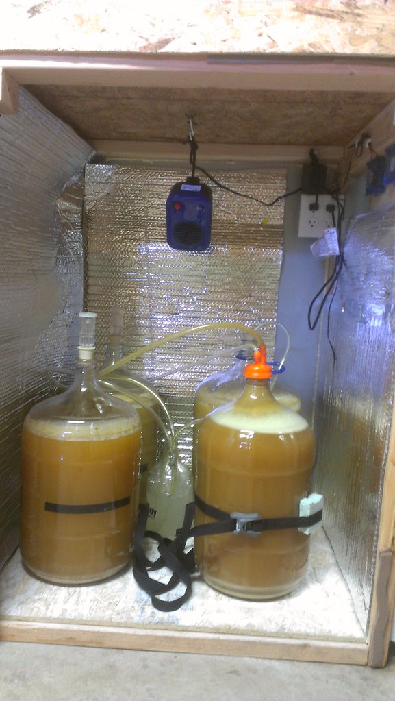
ebay aquarium temp controller build

Homebrew Talk - Beer, Wine, Mead, & Cider Brewing Discussion Forum

Help Support Homebrew Talk - Beer, Wine, Mead, & Cider Brewing Discussion Forum:

This site may earn a commission from merchant affiliate links, including eBay, Amazon, and others.
OK, I admit I didn't read every post in this thread so maybe someone already asked this question. I am wiring up my STC 1000 temp controller and I don't really need two outlets. I have modified the wiring diagram to show how I believe the hook up would go using one outlet with one receptacle for heating and one for cooling. Can someone give me a sanity check by looking at my revised schematic? By the way, I wanted to clean up the drawing with some white out but realized - we don't have that kind of stuff any more (nor typewrite ribbons!)

sc1000%2520temp%2520control.jpg

Disregard. Found this video.
What is the black vertical bolded line that is at the bottom of the schematic That all the hot wires run too.
 
Last edited by a moderator:
I want to buy two of these controllers to put in a 25 cubic ft chest freezer and then use one side for fermentation and the other for keg dispensing. Fermenter side would have a controller with heating element and keg side would have controller with the freezer plugged into it set at 36 f or 2C. Between them I would put foam insulation and insulate the sides of the freezer with foam on the fermenter side. How would I wire these two up? Diagrams would be helpful.

Also, has any one done it this way before with two controllers and two temp zones? I saw a guy do it with one controller and he used a heater that was on ALL the time in the fermenter side. Thanks!
 
Wooo ... finally got mine working ... after reading through all these pages there must be a dozen different ways to wire this thing. after multiple EE errors and re-wires its working the way it should 'i hope' for now.
 
What is the black vertical bolded line that is at the bottom of the schematic That all the hot wires run too.

Thats the power cable your plugging into the wall and you cut open...

Got mine working after struggling with a GFCI outlet that kept tripping my garage breaker...not sure if you cant plug GFCI into a GFCI outlet? The entire thing would work for 20 or so seconds, then trip the breaker in the garage...no matter what i did i couldnt get it to work. What confused me is i thought the entire point of GFCI was to trip the GFCI outlet, and not the entire breaker, but whatever.... The wiring ended up being different than any posted here, but its pretty straight forward when one side is "WHITE" and the other is "HOT"...never did wire into the LOAD side either...kind of disappointed...regardless i just went and bought a cheap $3 20 Amp dual plug and it works great...my freezer(Haier 7.1cu from Costco) probably holds temp for well over an hour..how long i dont know as i havent been around at the right times.

i need to see if i can figure out a way to actually measure how long its off and on without actually standing there, i know i could do something fancy like a Arduino or something but is there a ghetto way?
 
The entire thing would work for 20 or so seconds, then trip the breaker in the garage...no matter what i did i couldnt get it to work. What confused me is i thought the entire point of GFCI was to trip the GFCI outlet, and not the entire breaker, but whatever....

Unless your breaker includes GFCI, which is common (code?) these days, you had something wired incorrectly. If you have GFCI breakers, then there could have been an issue plugging a standalone GFCI breaker into an outlet controlled by the GFCI breaker.

The wiring ended up being different than any posted here, but its pretty straight forward when one side is "WHITE" and the other is "HOT"...never did wire into the LOAD side either...kind of disappointed...
?

i need to see if i can figure out a way to actually measure how long its off and on without actually standing there, i know i could do something fancy like a Arduino or something but is there a ghetto way?
Yes- put a beater couch in your front yard, open the garage, and watch while sitting in comfort and drinking 40's of OE.
 
For what it's worth, I ordered an STC-1000 from the seller in New York, and it got here in about three business days (I ordered it on the 30th of August, and it got here today).
 
For what it's worth, I ordered an STC-1000 from the seller in New York, and it got here in about three business days (I ordered it on the 30th of August, and it got here today).

Same, it took about 4 business days to get to me here in Oregon...i ended up ordering through NewEgg...nice thing was i accidentally ordered the 220V version but they sent the 110V version.
 
Hey there. I just finished building one of these guys. From what I can see I've followed the wiring diagram exactly. I have broken the tab on the hot side as well. The problem is that the socket doesn't seem to be receiving power. I tested it by plugging a lamp into the cold side and another into the hot. I assumed that one lamp or another should kick on. Does anyone have any clues as to what might be going on?
 
Hey there. I just finished building one of these guys. From what I can see I've followed the wiring diagram exactly. I have broken the tab on the hot side as well. The problem is that the socket doesn't seem to be receiving power. I tested it by plugging a lamp into the cold side and another into the hot. I assumed that one lamp or another should kick on. Does anyone have any clues as to what might be going on?

First thing that comes to mind is a bad connection somewhere. Are you using wire nuts? Check that all the wires are firmly in the nut by giving them a tug, maybe even re-twist. Do you have a multimeter to see where you are losing power? Does the STC1000 otherwise appear to work? You should hear a click as the relays turn on and off in the STC1000.
 
Did you out wait the compressor delay? That's generally the answer.

This guy's got it. Wait until the output light on the STC is solid, not blinking. Blinking = compressor delay. Most of us set it at 10 minutes.
 
Thats the power cable your plugging into the wall and you cut open...

Got mine working after struggling with a GFCI outlet that kept tripping my garage breaker...not sure if you cant plug GFCI into a GFCI outlet?

You cannot have two GFCIs on the same circuit, they will trip eachother.... (Just like you saw)
 
You cannot have two GFCIs on the same circuit, they will trip eachother.... (Just like you saw)

This is not entirely true. It's redundant, and many electricians and inspectors advise against it, but if wired correctly they will not trip each other.
 
eknee said:
Did you out wait the compressor delay? That's generally the answer.

Thanks I've been cursing this thing wondering where it was losing power, and this paper work they send is no help.
 
I have had numerous conversations with the electricians at my work about gfci breakers and gfci outlets (and witnessed issues mself). And I was told that if you have two gfcis on one circuit (gfci breaker, outlet, and/or gfci plug) you can have issues with constant tripping. Not saying something else isn't wrong, but just an idea if everything else is good.
 
I have had numerous conversations with the electricians at my work about gfci breakers and gfci outlets (and witnessed issues mself). And I was told that if you have two gfcis on one circuit (gfci breaker, outlet, and/or gfci plug) you can have issues with constant tripping. Not saying something else isn't wrong, but just an idea if everything else is good.

I've heard Mike Holmes saying that as well. . . :tank:
 
For what it's worth, I ordered an STC-1000 from the seller in New York, and it got here in about three business days (I ordered it on the 30th of August, and it got here today).

Ordered mine 2 days ago from the same seller. Should be here soon.
 
buzzman003 said:
Ordered mine 2 days ago from the same seller. Should be here soon.

I'm wishing I hadn't bought mine from China. It's been a couple weeks now and I'm getting impatient. Next time I will just pay the few dollars extra.
 
I ordered mine it took almost a month another
Friend ordered from the same guys lives 20 mins from me he got his in 4 days. Only positive I that is I've used mine, he's too busy to wire it up...
 
I think the GFCI discussion got muddled by the use of "cannot/will" where "shouldn't/can" would have been more appropriate, as was clarified later. Even my original 'could' would have read better as a 'may'.

That being said, using 2 GFCIs in series can cause issues, even when wired properly (for series). This can happen even when both GFCIs function properly when wired separately/in parallel. Several scenarios can cause this:
One GFCI has a current leakage lower than its trip threshold (or before its trip circuitry), and is wired downstream of a GFCI that has a trip threshold lower than the leakage (or the sum of leakages, if the upstream GFCI also has some 'post trip circuitry' leakage).
Any combination of the above resulting in a 'post trip circuitry' current leakage that exceeds the trip threshold of the upstream GFCI.

I have personally encountered this. I figured out which GFCI was problematic, and tossed it, even though it worked on its own. No sense in keeping something like that around. There could have been all kinds of reasons there was current leakage, none of them good.

These same issues can also be caused by faulty wiring external to the GFCI device as well, and this is a much more common cause.

Unless your breaker includes GFCI, which is common (code?) these days, you had something wired incorrectly. If you have GFCI breakers, then there could have been an issue plugging a standalone GFCI breaker into an outlet controlled by the GFCI breaker.
You cannot have two GFCIs on the same circuit, they will trip eachother.... (Just like you saw)
That doesn't make sense to me. Could you provide an explanation or justification for your statement?
This is not entirely true. It's redundant, and many electricians and inspectors advise against it, but if wired correctly they will not trip each other.
And I was told that if you have two gfcis on one circuit (gfci breaker, outlet, and/or gfci plug) you can have issues with constant tripping.
I've heard Mike Holmes saying that as well. . . :tank:
 
.....That being said, using 2 GFCIs in series can cause issues, even when wired properly (for series).......
I agree with the rest of your post but I can't imagine why one would wire ANY receptacles in SERIES, much less a GFCI. Residential power distribution is strictly a parallel game. If any receptacle is wired in series with another receptacle, they share the voltage and most, if not all, appliances would not function.

Now that I think about it, maybe I'm just misunderstanding the terms being used. By "series", are we talking about a gfci attached, in parallel, to the LOAD side of an upstream gfci? If that's the case, then, in theory, there should still be no issues. Of course, if one of the gfcis is not functioning correctly, then all bets are off.

A gfci constantly compares the current in the LINE hot and neutral conductors. If that current is unequal by more than about 6mA then it trips. It is assumed that extra current is traveling to ground through some other path. The LOAD terminals simply extend that monitoring to downstream receptacles.
 
Right now it's underneath the door seal, with something heavy on top of the lid. Now that I have my dual-stage controller (been sitting in the packaging for the past month, since I'm moving this weekend), I'll be doing something I haven't seen before - I'll post pics when it's done.

emjay - Did you ever post pics of your build? I read multiple times that you had something big planned, but never saw a post in this thread with the final product.
 
gar2376 said:
emjay - Did you ever post pics of your build? I read multiple times that you had something big planned, but never saw a post in this thread with the final product.

How dare you hold me accountable?! :tank:

Ha, no. I scrapped the entire thing as I'm putting together an ebrewery and I figured I might as well integrate the fermentation control while I'm at it.
 
Residential power distribution is strictly a parallel game. If any receptacle is wired in series with another receptacle, they share the voltage and most, if not all, appliances would not function.

Now that I think about it, maybe I'm just misunderstanding the terms being used. By "series", are we talking about a gfci attached, in parallel, to the LOAD side of an upstream gfci?
I may have (did) bastardized the terms a bit (a lot), but it was the best I could come up with, especially if you read it in the context of multiple GFCIs and subsequent upstream/downstream descriptors. I was hoping to avoid a 2 page explanation of line, load, losses, op amp summers, etc. When read in context of upstream/downstream it should make sense.

When plugging in his controller box built with a GFCI into the outlet (which may have been controller by a GFCI breaker), he was essentially wiring the downstream GFCI to the 'load' terminals of the upstream GFCI (my bastardized 'series'), instead wiring the downstream GFCI in a 'pigtail' fashion to the line terminals of the upstream GFCI (parallel).

If that's the case, then, in theory, there should still be no issues. Of course, if one of the gfcis is not functioning correctly, then all bets are off.
I said as much, and more, in my previous post. There are occasionally small current leakages in outlets, and I would guess they may be even more common in GFCI outlets, especially on the line side. Different makes and ages of GFCIs have different trigger levels. I hear that newer ones actually have higher trigger levels than older ones, and this may have been done to help with false triggers of all sorts. I can't think of any other reason to raise the trigger level. I assume the speed/reliability of the circuitry increased, allowing them to safely raise the trigger level while maintaining safety factors.

A gfci constantly compares the current in the LINE hot and neutral conductors. If that current is unequal by more than about 6mA then it trips. It is assumed that extra current is traveling to ground through some other path. The LOAD terminals simply extend that monitoring to downstream receptacles.
Exactly, and that is why both the line and load losses (if any), from the downstream GFCI are added to any load losses (if any), from the upstream GFCI, which can trigger the upstream GFCI when a second GFCI is wired downstream.
 
Has anyone exceeded the 10 Amp rating on this? I was planning on using a hair dryer for the heat on this, and I looked at it today and saw that it draws 15 Amps.
 
Has anyone exceeded the 10 Amp rating on this? I was planning on using a hair dryer for the heat on this, and I looked at it today and saw that it draws 15 Amps.
Open the case on your unit (after unplugging it). Check the relays. They may be different than 10A. Mine are 15A. That said, a small space heater can be had for very cheap at walmart/target/big lots/kmart/etc.
 
Open the case on your unit (after unplugging it). Check the relays. They may be different than 10A. Mine are 15A. That said, a small space heater can be had for very cheap at walmart/target/big lots/kmart/etc.

Bingo! These are actually 15 Amp @ 125 VAC relays. Thanks for your help!
 
My pleasure but I would worry about a hair dryer overheating. A small space heater may work better. Or even just a light bulb.

Well I'm certainly open to consider other options if they're effective.

One reason behind selecting a hair dryer is that it heats up fast, thus it won't have to stay on long.

My other reason is that the fan is built right in to it. I'm going to have computer fans run while the Cold is active, the hairdryer would prevent me from needing separate fans (and a separate power supply) when the Hot is active.

I don't really like the idea of a space heater because they're on the larger side. I've considered light bulb/heat bulb and those lizard heat ropes, but that causes problems for my planned fan system. I have an old computer power supply I'm going to use to power my fans when cold is active. If I had a heat source without it's own fan, then I'd need to run the fans when hot is active too, which I believe I can't do unless I plug those into my always-on outlet.

Perhaps I am just over-engineering this thing. I could plug the fans into the Cold outlet in summer, and the Hot outlet in winter. This would allow me to use a simpler heat source.
 
What is the drawback to running the fan at all times? I have a 12v computer fan wired into an old 9 volt cordless phone power supply. Works great for me.
 
Just trying to avoid the constant power consumption, though it should be relatively small. I'm also planning to wire up 4 fans total. 2 for circulation inside the chamber, and 2 to move air across the condenser coils for my refrigeration unit. What I would really like is a way to run all fans when Cold OR Hot are running. I don't believe that is possible though.
 
Just wire up an additional outlet that is not wired through the controller.
Since my fridge will be indoors I won't need heat, so I have one outlet wired hot, and the other switched with the controller for refrigeration control.
Same could be done using an additional outlet if you want to have constant on + cool + heat.
 
I second the small space heater idea. I use one. It's small. It has a flat bottom for it to stand on, unlike a hair dryer. Here it is inside a mini fridge beside a carboy.

image-4252414763.jpg
 
I picked up a small lasko heater from Walmart for $13 that I use in my chamber. I actually have it hanging from the ceiling of the chamber just in case there is a blow off or something that would cause a puddle on the floor. This way it's also not aimed directly at any of the carboys which could cause uneven heating.

7983753794_9c17d9529b_b.jpg
 
I picked up a small lasko heater from Walmart for $13 that I use in my chamber. I actually have it hanging from the ceiling of the chamber just in case there is a blow off or something that would cause a puddle on the floor. This way it's also not aimed directly at any of the carboys which could cause uneven heating.

Using separate DIY fermwraps and controllers for the least active ferms would keep ferm temps much more stable. There is no way to control more than one fermentation in a single chamber without using this method, or its equivalent. Peak ferm temp is ~10F above ambient. The fan will help reduce that differential some, but even if all but one are in the clean up phase, the temps in those will be dropping, possibly causing the yeast to slow down. Probably not a huge issue if all but one is finished, but a much bigger issue if two are going at once that were pitched a few days apart.
 
cwi said:
Using separate DIY fermwraps and controllers for the least active ferms would keep ferm temps much more stable. There is no way to control more than one fermentation in a single chamber without using this method, or its equivalent. Peak ferm temp is ~10F above ambient. The fan will help reduce that differential some, but even if all but one are in the clean up phase, the temps in those will be dropping, possibly causing the yeast to slow down. Probably not a huge issue if all but one is finished, but a much bigger issue if two are going at once that were pitched a few days apart.

I was planning to do something like this but was unsure of its feasibility. My plan was to control the chamber itself (cooling) with a probe on the fermentor that I want to have the lowest temp, and fermwraps on everything else, in order to be able to specifically control different fermentations exactly how I want, in a single chamber. I'm a bit concerned that I might not be able to get a significant difference in temp between the coolest and warmest fermentations though. Thoughts?
 
Back
Top