Automated HERMS system

Homebrew Talk - Beer, Wine, Mead, & Cider Brewing Discussion Forum

Help Support Homebrew Talk - Beer, Wine, Mead, & Cider Brewing Discussion Forum:

This site may earn a commission from merchant affiliate links, including eBay, Amazon, and others.

blackheart

Well-Known Member
Joined
May 4, 2008
Messages
315
Reaction score
19
Location
Binghamton, NY
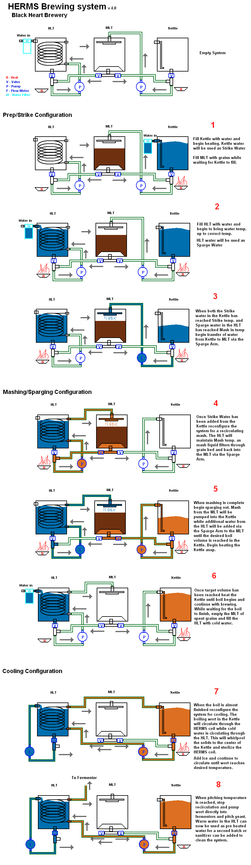
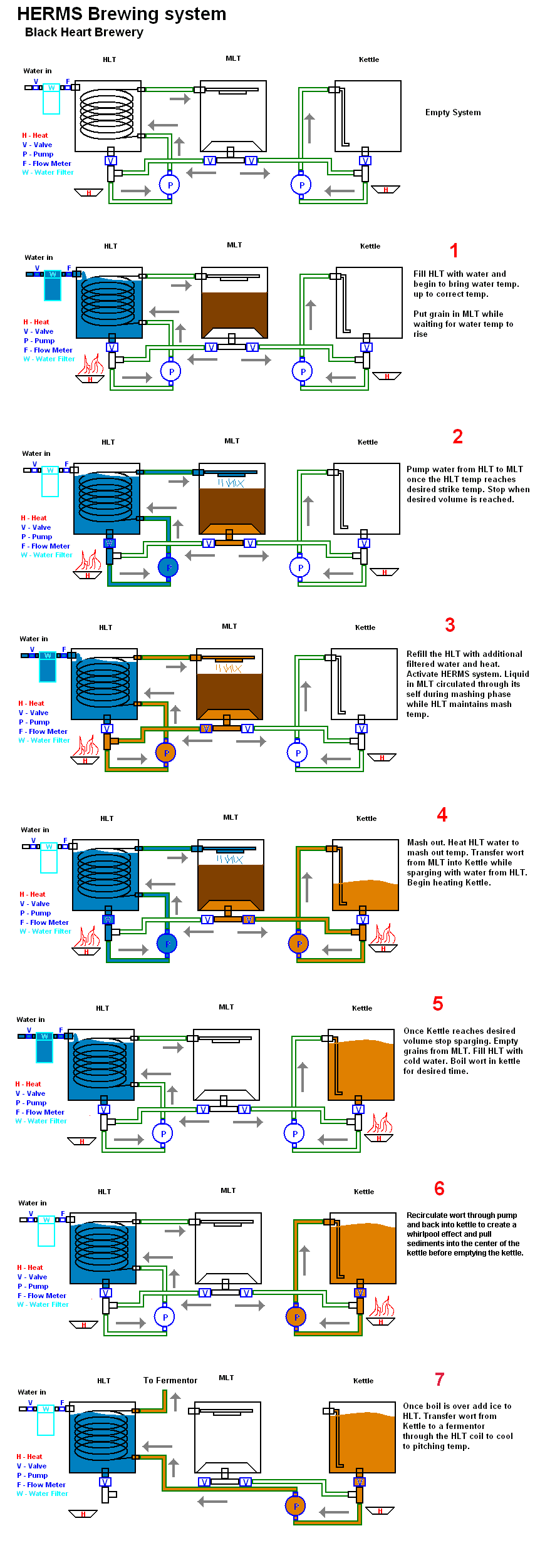
We are attempting to construct a new brewing system now that our small home brewery is nearly complete. I started a new thread for this HERMS system but it is a continuation of this older thread when we were considering RIMS.

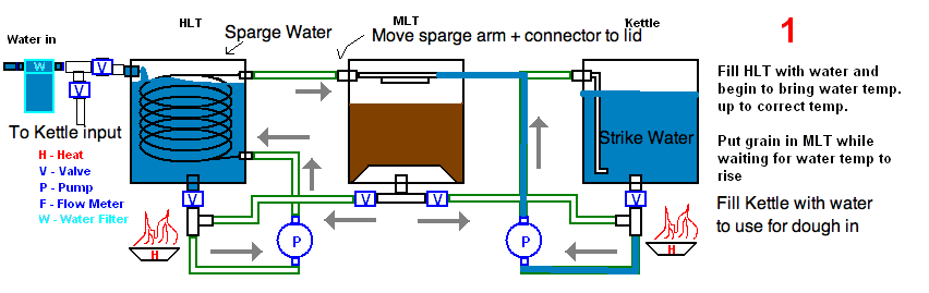
Anyway here is the outline of how the system will operate.
HERMSv3.png


We are working on figuring out each and every part we will need to order. Here is an example of one of the parts assembly pictures we are working on. This would be the bottom valve on the HLT and Kettle from the image above. Everything is 1/2" MPT

partAssembly.png


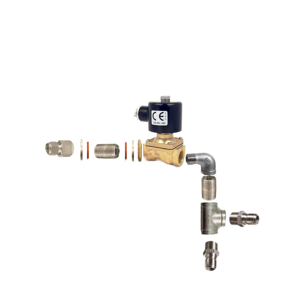
Kind of guessing on build our own bulk heads there. Compression fitting inside let us connect to SS tubing to make a dip tube or to connect to a coil etc. The threaded pipe is a 1" piece of 1/2" MPT I assume it needs a washer and O-ring on either side with a nut on the outside and a compression fitting on the inside. Hopefully there is enough thredding left over to thread it onto the valve. This would be a 12v 1/2" SS electronic valve that can handle 200+F

We are looking for some feedback/suggestions/comments on this system so we can make any final revisions before placing orders. Thanks!
 
One thing you might want to think about is initially filling your MLT from your BK... which is how I do it.

... if not, you're going to have to refill your HLT to submerge your heat exchanger. (oops... I see you list that step)... it's still something to think about though. That's how I have my rig set up and I like the way it works.

Plus... if you build it so you fill from the BK, you can step mash a lot easier by using both infusions and raising the temp in your HLT.
 
In step 3 you refill the HLT with cold water and reheat. You won't be able circulate mash through the HERMs coil until the HLT water is heated to mash temperature otherwise you'll cool your mash. How long will that take and is your MLT insulated to help retain heat before the HERMs coil is up to mash temp?
 
Why not put water in your BK and hold It at temp to refill the HLT, or fill the MT from the kettle.
 
I think that looks like a slick plan. Two points:

1. I would strongly consider a hop back.

2. Are you using QD's, hard plumbing, or a mix of both? It seems like you may be able to simplify the system if you hard plumb the outputs to the pumps. If you check my blog for a couple of the builds I have designed you will see how I use a combo of hard and soft plumbing to simplify the systems. You may not like it, but it is worth considering IMO.

I am soooooo jealous of the speed with which you are putting all this together. You are my hero!!!
 
Well after looking at your flowchart which looks like you took some time to put together (great job) I would question steps 1, 2 and 3.

My thought would be the following:
Step 1: Fill both the HLT with water and the MLT with enough strike water and raise the heat in both at the same time.
Step 2: Then once your MLT is up to temp then add grains to the water.
Step 3: Once you mash in then start the herms system to keep the MLT at correct temp.

Then proceed to step 4 and beyond. This is just my 0.2cents but I am in the process of starting to build a HERMS system soon and found your post to be very informative. I also subscibed to this post to see the final out come. Keep us posted. :mug:
 
OK let me see if I can answer everyones comments and suggestions in one post!

First of all, the idea of using both the kettle and HLT to create hot water to use for sparging etc is a great idea. I will re think the connections a little to see if I can get it to work automatically. It sounds like it will save a good deal of time and be much more efficient.

yes, I plan on insulating everything I can to maximize efficiency. So all 3 pots will be insulated, and hoses etc where I can without interfering with normal operation.

We plan on hard plumbing everything all the way out to male 1/2" SS QD's. They looked nice because they had no internal shutoff valve and looked easy to clean. Then we are using the Hi temp plastic 1/2" tube to make F/F "jumper" cables to connect everything together.

I picked up a 28$ water filter + housing on sale at Lowes that people have been using to make hop backs with. We are planning on using it as a water filter to get water in from a hose. We were thinking about hard plumbing it into the side but if we are putting filtered water in both the HLT and Kettle then something more like this would be better.
https://www.homebrewtalk.com/f51/water-filter-setup-29145/
and then we could move it from one to the other without hassle.

BTW Boerderij, where can I find your sketchup models? I liked your parts diagrams you made and we are making a similar one for this project. Does the layout look correct for weldless fittings with the Compression fitting - washer - O ring - keg - O ring - washer - Nut
 
For the weldless fittings I go :

Female threaded component (e.g., half coupling) - SS washer - keg wall - Silicone O-ring - Locknut - female threaded component (e.g., ball valve)

If you size the hole properly (close fitting) then this arrangement will give you leak free service and a completely solid connection. I have never had a leak that way and my fittings do not wiggle at all.
 
OK so I took about 5 minutes to redraw the initial step 1 with a different paint program just to give a rough idea of what I was thinking of.
HERMSv3_1.png


A few changes. First there would be 3 configurations, prep, mashing/sparging/boiling, and cooling. Each of these would require some moving of hoses etc. Since I want to make everything the SS QD's this should all work out well. The initial configuration would look like the one above. The major difference is that we would move the sparge arm and connector from inside the keg wall to inside the lid or in the center front/back of the keg. This is so either the Kettle or the HLT can easily connect to it.

The coil would be disconnected from the MLT in and the output of pump 2 from the kettle would connect to the MLT in insead. The Kettle would be used to provide strike water and filled with water first to get things progressing faster. When the HLT has water filled and hits the target temp then the recirculation could begin as shown previously with one simple hose change.

I also changed the water filter configuration. Putting two valves on the filter would allow us to mount it down lower by the pumps and then run two separate connections to the IN ports on both the Kettle and HLT or use one valve and manually switch the hose.

So basically if I keep all the connections a standard 1/2" male QD on all the equipment then I can always connect any part to any other part with the same tubing.

Boerderij, so let me get this strait. Instead of sandwiching the keg on either side with an O ring and a SS washer, you have a SS washer inside with no O ring and a O ring on the outside with no SS washer, just a lock nut, and this works fine?

You dont need a O ring on the inside and outside? The lock nut does not need a washer and does not chew into the O ring?
 
You thinking is correct.

Here is an example:
Part_list_drawing.bmp


The key is to buy locknuts with a groove machined intot he back side. The groove holds the o-ring in place without smushing it.

The other key is how you install the locknut. When you tighten it, just snug the locknut as hard as you can by hand, then instead of turning the locknut to tighten it, turn the fitting on the inside like it is a nut you are threading into the locknut. This way the locknut and o-ring remain stationary and the nipple threads into the locknut thereby compressing hte o-ring and forming a seal. Then, the last step is to just give the locknut a small turn to really lock it in place. Maybe buy one or two extra o-rings as it may take a practice or two.
 
Ah! I get it now. Thats great. I thought I was using too many parts there. Thanks for linking the picture. I was looking through you blog posts, you have some good stuff in there. Thanks for the info. The sketchup models would be great whenever you get a chance.
 
You're going to use ice in the HLT right? If not, how are you going to cycle hot water out? You'd also want a stirrer to agitate the HLT water during HERMS operation and ice during the cooling phase.
 
Subscribed, looking forward to what you do. I want to echo the "how automated" question, push button, programmable?

I had another question...ummm.... oh! Maybe consider a "drain valve" after the MLT so you can collect extra wort once you have your pre-boil volume? Think yeast starters:)
 
I am setting up a very similar system. I like the idea in step 7, I didn't even think of that. Do you think the wort will be cool enough? You may have to recirc back to the boil kettle, just a thought . You may want to add a hop stopper to control the trub flowing through the lines. I subscribed as well and look foward to your outcome.
 
I could be way off but I don't think you'll get anywhere near a pitching temp with just one pass through of the coil in the HLT... even with ice.

I have a 30 plate chiller that works really well but it certainly won't get there on just one pass.

Like I said, I could be wrong though... maybe someone has a similar/same set up that can comment?
 
With the HLT full of ice and then full of water, the wort should come out at pitching temps or lower. The problem is having to stand there with a mash paddle and move that ice around really well as it's flowing. Depending on the batch size, some water may need to be removed and replaced with ice at some point. A more automated approach would be to use a plate or CFC and pump the HLT icewater in as the coolant.
 
The simplest solution is to circulate the ice water with the second pump you already have.

Also, you could salt that water if you really need more cooling power.

I am a proponent of full volume cooling so I would suggest whirlpooling the cooled wort back into the BK. .02
 
Thanks for the questions and feedback everyone. I downloaded many of Boerderij's sketchup files so I hope to have a sketchup model when this is done to put in our sketchup model of the brewery!

For a flow meter I think we may just use simple float valves on all 3 pots. One small (1.5bbl) brewery we have talked to does everything manually but for sparging they connect the HLT water pump into the mash, controlled by a float valve in the MLT. Then they control the speed of the MLT being pumped to the kettle manually. This way when the Mash water level dips below a certain point the pump kicks in and adds more water so there is less to control.

We plan on using an Arduino based micro controller to handle everything. I currently have a Arduino Mega and a Sanguino which both support many connections and decent storage space. I have done some preliminary testing with both. Ideally there would be as few physical controls as possible. 4 buttons and a LCD screen to display basic status.

The real brains of the operation would be a computer/iPhone on the other side of things. Using the iPhone/website you would be able to build a recipe, predict it's results, and click *Brew*. The website/iPhone app would then communicate with the brewing system over ethernet and send it a set of instructions which make up the recipe in a way that it can understand. The arduino will not know that your using 4oz of Cascade hops but it will display that as text on a screen and it will know to prompt you at the right time to add the hops to the boil.

The arduino will handle some basic automation like temperature control. It should be able to figure out how to hit a specific temp as fast as possible without overshooting it and stay there for a specific length of time. It will also be able to use PWM to control pump speed and open and close valves.

During the brewing live data from the sensors as well as estimated time to completion, phase, next step, etc will display in some basic form on the LCD on the brewing system. All of the data will also be sent over ethernet to our web site where anyone can view the live progress of us brewing. Info will then be sent from the web site to the iPhone app. which will be best able to provide in-hand monitoring of the process, alert us of critical warnings/temps and provide us with unlimited virtual buttons to control all equipment manually.

So once everything is connected and wired up step 1 is being able to control everything over ethernet and reading data from all sensors. From there I think we will be doing lots of tests to pretend to be the brains of the system and manually turn on and off pumps and valves etc until we have the process down. From there we will automated it with the arduino making as many decisions on its own as it can.

We definitely plan on brewing with our system before its fully automated as automation will really be a work in progress for a while.

In regards to recirculation and stirring of the HLT and the Kettle.... The HLT and Kettle may both have a stirring motor each to help keep temperatures consistent. During the cooling phase where we change connections around to use the HLT as a chiller, we can simply connect the HERMS coil out back into the Kettle In at the end of the boil, this will sanatize the inside of the coil and create a continual flow of wort in a closed system. Then we add cold water and ice to the HLT and connect pump one, which is not in use at the time, from the HLT out to the HLT in and recirculate the ice water back on itsself or use a stirring motor. This way we can have basically a large recirculating counter flow chiller. Also, we have what is basically an A/C unit that runs through a cooler with 1/2" hose going in and out of it, which uses the A/C unit to prechill hose water or to help keep the ice water cold while recirculating it.

Like I said before, I think that if we use all of the same fittings we can always reconfigure how things are connected down the road.

I'm looking forward to finishing up the parts layout and posting it up here. Hopefully others will find some useful ideas in what were doing here as well.
 
Silly question if this has already been addressed or is implicit in the design, but how do you know you've reached your intended mash volume if you're mashing with the grain already in there? Are you looking at how much water goes missing from the HLT?
 
Excellent question. We could use a few different ways to measure the mash volume. A float valve/looking in the Kettle might show the lost water difference. We also may want to just do it by sight... like fill past the grain level a certain amount. Is the initial mash volume important? I feel like a high temp flow meter is going to be expensive.

Here is a picture of the connections and procedures to brew with all the enhancements everyone has suggested. All of the parts are the same, the configuration of the hoses changes only 3 times. Other than that the actual brewing should be automated.

What do you think?

HERMSv4.png
 
Are you going to physically attach a new line between the BK and HLT for the cooling part?

EDIT: I see I guess you're disconnecting the sparge arm or whatever that is, and moving that line?
 
You might want to look at BeerThirty's rig, 3 keggles, 6 solenoid valves in wort/water paths and 2 pumps, with no plumbing changes needed during brewing. Add in pressure sensors for level control electric burner ignition, and solenoid valves for fill water, cooling water control to plate chiller for a complete mobile system controlled by the Brewtroller.
 
In your newest iteration I have a concern. In step 7 you recirculate the boiling wort to sanitize the herms coil for cooling. It won't sanitize if the HLT is full of cold water at the time, it'll cool the wort below sanitizing temps. Best to circulate with the HLT empty first, then add the ice and water at flame out.

Otherwise, your rig is getting slicker and slicker.

Cheers
 
You might want to look at BeerThirty's rig, 3 keggles, 6 solenoid valves in wort/water paths and 2 pumps, with no plumbing changes needed during brewing. Add in pressure sensors for level control electric burner ignition, and solenoid valves for fill water, cooling water control to plate chiller for a complete mobile system controlled by the Brewtroller.

... that's how I did mine... only I have nine solenoids because I wasn'y smart enough to make it efficient enough to just use six.

That's what I was asking before on how automated this was going to be... "just flip buttons" vs "brew while you're not there"

I can sit on a chair and other than dumping in grain, stirring once or twice and adding hops... all I do is flip switches.
 
I posted on beer thirty's thread about his new system but its short on details. we would like to make it as automated as possible, with the exception being to add grains and hops.

How did/would you connect your system to be automated Cape Brewing?
 
I posted on beer thirty's thread about his new system but its short on details. we would like to make it as automated as possible, with the exception being to add grains and hops.

How did/would you connect your system to be automated Cape Brewing?

I would simply need a computer to run all of the switches, put in some sort of flowmeters for volume control and then build something to do my hop additions. Everything else is done.

A motorized mash rake would also be a good-to-have. I have the motor but never bothered to build a rake or hook it up

I quick connect a hose to one end that runs through a water filter and then it hits the first solenoid.
- fill HLT - a switch
- fill BK - a switch
- bring HLT up to temp - type in temp on PID
- bring BK up to temp - type in temp on PID
(I have two 32 tip jet burners on pilot and they run off the PIDs)
- fill MLT from BK - a switch
- add grain (or simply have grain already in there)
(motorized rake would be needed if going fully automated)
- circulate MLT through heat-ex in HLT - a switch
- mash out - a switch
- sparge - a switch
- boil - jack PID up over 212 degrees
- Chill - a switch (although I would have to have one more solenoid that ran water to the chill plate... right now I hook up a hose manually... so I guess I lied... it's not ALL flip a switch).
- pump into fementer - a switch.

so I plug a hose into one end... flip a bunch of switches... and cooled wort comes out the other end.

Or are you looking for a schematic?
 
a schematic of how you connected everything together so there are no (or just one) hose change and the rest is flipping switches would be amazing. Basically we are going to construct it as a manual flip the switch to do something then get the micro to control the switch flipping and incorporate the PID controls.

Also, any info you have on electronic valves would be great. Valves for the gas and liquid both. Does your PID do a good job of ramping up to and hitting the right temps?

Thanks for the picture kladue. I am assuming that the system is not HERMS and that the connections are simplified in that picture, so I dont know if it would work but the idea that there could be semi permeant plumbing and no hose changes appeals greatly to us.
 
My rig is direct fire RIMS, but it would not take much to reroute a few feet of tubing to make it a herms with the addition of a HE coil in the HLT. The plumbing can indeed be permanent without hose changes, mine is. We just added some teflon tubing to allow the tuns to be tipped for cleaning without disconnecting any plumbing. Once the control box is finished the only thing I will have to do is add hops(auto carousel to come in the future) and move the chilled wort hose from recircing the BK to fill the fermenters.
 
a schematic of how you connected everything together so there are no (or just one) hose change and the rest is flipping switches would be amazing. Basically we are going to construct it as a manual flip the switch to do something then get the micro to control the switch flipping and incorporate the PID controls.

Also, any info you have on electronic valves would be great. Valves for the gas and liquid both. Does your PID do a good job of ramping up to and hitting the right temps?

Thanks for the picture kladue. I am assuming that the system is not HERMS and that the connections are simplified in that picture, so I dont know if it would work but the idea that there could be semi permeant plumbing and no hose changes appeals greatly to us.


Gotcha.. (I was praying you weren't gonna say that).... I made it all up as I went along so I don't have a skematic but.. yeah, I'll sketch somethin' up. I can get you the link for the liquid solenoids as well. I have two Honeywell gas valves that hook into my PIDs for gas flow. I can get you the part #'s if you want.

I'm all hard-plumbed with no hose changes.
 
BeerThirty's rig uses teflon tubing for all the flexible connection requirements and does not need any plumbing changes during operation. If you want to do HERMS/RIMS just connect it to the pump circuit to the mash tun. For step mashing do the direct fire routine to get necessary heat input for quick step and let HERMS maintain temperature by cycling pump.
As to liquid system valving, which method of control do you want, 2 position or proportional control, Belimo for proportional, STC solenoid for 2 position. For the gas control valves, what pressure and type of burners do plan on using. If you stay under 1/2 PSI (Low pressure propane-NG) then low voltage furnace valves will work, if greater than 1/2 PSI then you again need solenoid valves.
As to the operation of BeerThirty's rig you have to ask him that as I only assisted in the construction, he is using a BrewTroller to operate everything which seems to be a good match for that type of system.
 
Back
Top