2 PID 50a Control Panel Design Check

Homebrew Talk - Beer, Wine, Mead, & Cider Brewing Discussion Forum

Help Support Homebrew Talk - Beer, Wine, Mead, & Cider Brewing Discussion Forum:

This site may earn a commission from merchant affiliate links, including eBay, Amazon, and others.

ironmountainbrew

Active Member
Joined
Sep 28, 2011
Messages
39
Reaction score
0
Location
Festus
I'm hoping to get feedback on the layout and functions of my control panel. My plan is to be able to run 2 - 5500 watt elements along with two pumps at the same time. I want to power on the PIDs with the main power switch.
The PIDs I'm using have built-in timers, so I'm including a reset button for each.

Here's a rundown of the panel switches and LEDs
  • 22mm LED - [1 - green (power), 1 - red (alarm), 2 - blue (pumps)]
  • 22 mm Flashing Buzzer
  • 22 mm LED Push button Switch - [2 - yellow (elements)]
  • Push button Switch, Momentary - [2 - red (PID Alarm Reset)]
  • Emergency Stop locking push button
  • 2-Way Switches [ 2 - pumps, 1 - alarm]
  • Key toggle Switch (panel on/off)

Please let me know if I'm missing anything obvious.

Also, It would be great if someone happened to have a wiring diagram that fit this build.

Thanks in advance. :)
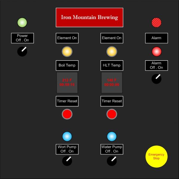
Control Panel.jpg
 
Ironmountain,

Your idea looks great. Running both 240v 5500w elements at the same time along with pumps, etc, you'll be right near the top of your 50 amps.

Regarding your PIDs and alarms. You have timer reset buttons for each PID, but only one alarm. Is the alarm common for both PIDs? You also have an alarm on/off. Is the objective to disable the alarm? Why? You didn't say which PIDs you have, but if it's the Auber 2451 with the built in timer, when you reset the timer it stops the alarm.

I completed a build similar to yours a couple of months ago. The only difference in my setup is I have an extra PID used for my RIMs tube and I use illuminated push button switches instead of toggle switches with indicators.

P-J has created many schematics for us to use. Reach out to him for assistance there.
This one is close for your system. It does not have the timer buttons on the PID.
Auberin-wiring1-a7-SYL-2362-5500w.jpg


Check out the link in my signature for my build. I think the plans are in there too.

Good luck!
 
stlbeer,

Thanks for the feedback.

The alarm part of the build is the only thing that is confusing me. I'm not sure the alarm on/off is necessary, but have seen it in similar builds. (I guess I would always want the alarms I set to trigger.) I assumed the reset on the timer would turn the alarm off, but wasn't sure about resetting the alarms triggered on temp. I think a common alarm for both PIDs would work just fine, but like the idea of having the two reset buttons. I'm planning on using the Auber 2451 PID with the built in timer. Here's the list of items I would like tied to the alarm. 1) HLT strike/sparge temp reached 2) Mash rest times 3) Boil additions 4) Boil complete

BTW: After using the 2451 PIDs, do you recommend using them for the timer, or would you opt for a separate timer? How are they as far as being able to monitor your BK times?
 
The alarm part of the build is the only thing that is confusing me. I'm not sure the alarm on/off is necessary, but have seen it in similar builds. (I guess I would always want the alarms I set to trigger.) I assumed the reset on the timer would turn the alarm off, but wasn't sure about resetting the alarms triggered on temp. I think a common alarm for both PIDs would work just fine, but like the idea of having the two reset buttons. I'm planning on using the Auber 2451 PID with the built in timer. Here's the list of items I would like tied to the alarm. 1) HLT strike/sparge temp reached 2) Mash rest times 3) Boil additions 4) Boil complete

The reset on the timer does turn off the alarm, but I only use them or timer, not temp. I use them for mash rest times, boil additions, and boil complete. I suggest downloading the SWA-2451 manual from Auber and closely reading the section on the timer and alarms. It is configurable in many ways and you need to decide what you want to do with the available options.


BTW: After using the 2451 PIDs, do you recommend using them for the timer, or would you opt for a separate timer? How are they as far as being able to monitor your BK times?

I like using the integrated timer. I have 2 of them, one for my RIMS and one for the BK,though I really only need 1 since the timer function is disabled when the PID is put in manual mode. Manual mode is used when the wort starts to boil. I'll reduce the percentage of power on to about 65%.

I have the standard Auber SYL-2352 for my HLT and I'm considering switching the BK and HLT PID's so I can then use the timer on the HLT PID to time the boil. This way I can accomplish back to back brews - having the RIMS time the second mash and the HLT timer to time the boil additions/boil.
 
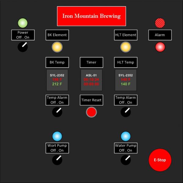
I'm seeking a wiring diagram for the following two PID + Timer 50amp build

PID: Auber SYL-2352
Timer: Auber ASL-51

My plan is to follow P-J's advice and use a SPA panel for the main power feed. I want the PIDS and timer powered on by the main power switch. The elements are switched on by an illuminated push buttons and can both be powered at the same time. The single alarm is activated by either one of the PID’s temp alarms, or the timer and can be turned off by either one of the temp alarm switches or the timer's momentary push button switch. I also like the idea of having an E-Stop on the panel.

I would like to use a 5500watt element in the BK and the HLT, but I'm wondering if this might cut things close, so perhaps one 5500watt element and one 4500watt element.

I'm nearly ready to go with the exception of one or two more components and a wiring diagram that fits the build. Everything is DIN mounted with the exception of the SSR's.

If anyone sees any obvious flaws in my layout, or has a wiring diagram that fits the build I would greatly appreciate the feedback.

Sincerely,
Ryan...

Control Panel_V7.jpg
 
thanks stlbeer.

I think I will reach out to P-J to see if he has anything. Your schematic is really close to what I'm doing. I just need to figure out the timer and alarm part. I've been browsing post here for months now to get an idea of what I want and how to do it and of course have realized that P-J is the master of electricity. His schematics are easy to follow and his advice on components and safety measures are priceless. I just haven't run across a schematic that fits my build exactly and I'm too dumb to figure it out on my own. :p
I subscribed to this thread a while ago & your ideas sparked my interest.

I've developed a diagram that 'almost' fits your desired plan. Your plan (in post #5) is rather complex and it requires a lot of additional components that would not normally be required.

The one item of major concern is the "Power On/Off" switch. This adds a lot of complexity to the design with multiple contactors involved to implement it.

The other is the managment of the alarm set up. That requires a lot of additional components and a design that is very difficult to implement (for me). I'm close but not anywhere near your plan in post #5.

Oh well... It was an interesting adventure for me anyway. I've been messing with it since about 5 this morning.

Wishing you the best in the planning of your build.

P-J
 
To get amps, divide power in watts by voltage. 11000 watts will take 45 amps at 240V, 10000 will take 41.5, and 9000 will take 37.5. I would shy away from 11000 watts on a 50 amp circuit. Also, I would keep it on 1 circuit, not 3 as shown above. You don't want to have 3 power cords going to your panel!

I built almost the same panel as you minus the alarms. Not that I know the difference, but I don't miss them.
 
What are you drawing the panels in? I would love to have that software if I dont have it already. Wiring those panel is actually easier than it appears at first. Just gotta set up the basic frame work in and out, then add in the leds and the nice to haves. I'm still learning basic (very basic) electronics, but with the PID's it is much easier to build a panel and control system. Thanks for the good lookin panel pics!!! Gave me some ideas on how I want mine laid out when the time comes. I'm still gathering parts and learning how to make usefull and safe circuits.
Have a great brew week!!!!
Wheelchair Bob
 
Could you use the Auber SYL-2352 PID's for the HLT and BK and then use the Auber 2451 w/ the timer for the mash tun so you can still get the temp? And since you don't have to use that in manual mode, the timer will always work.
 
ironmountainbrew,

You mention in your first post
- Key toggle Switch (panel on/off)

Is that something that you still want to incorporate in your panel design? I think it is a good idea. (Especially if you have children in the house.)

I'm still messing with a custom diagram for you and am getting a lot closer with the plan. I'm just dealing with the nitty-gritty now. (I'm hunting down a 50A DP contactor at the moment to implement the Key switch requirement.) I'm also messing with the alarm set/reset functions.

I think the plan will result in a really nice electric brewery set up for you. I also thank you very much for the mental challenge that you presented to this 'ole man. This kind of "stuff" is what keeps me going.

Please let me know.

P-J
 
P-J,
Thanks so much for taking interest in my post. Yes, I would like to incorporate the key toggle switch for the on/off, but I'm also open to suggestions if it over complicates the build.

Rbeckett, I'm just using Visio to mock up the panel layout. Thanks for the compliments.
 
ironmountainbrew,

Ok. Here is a diagram for your planned build:

As always - Click on the image to see (and save) a full scale diagram that is printable on Tabloid paper (11" x 17")


I sure hope this helps you in your adventure. If you need anything changed on the diagram, Please let me know.

P-J
 
P-J,
Your contribution of countless hours dedicated to this community is absolutely priceless. I'm sure a lot of the electric brewers out there would still be on propane if it weren't for you.

Thank you for putting this together. This is awesome! The only differences of what I had planned was 1) I wasn't planning on using a power switch for the PIDs and 2) I'm going to use illuminated switches for the element on/off instead of the separate switch and LED power indicators. Unless there is a reason I can't make those changes, this diagram is perfect.

Thanks again for all of your help.

Sincerely,
Ryan...
 
Ryan,

Ok. This is the updated diagram with the changes you requested:

As always - Click on the image to see (and save) a full scale diagram that is printable on Tabloid paper (11" x 17")


I hope this reflects the changes you wanted.

P-J
 
P-J,
This is perfect. I'll be sure to post pictures of my progress here in case anyone else is wanting to do a similar build.

I can't wait to get started.

Thanks again.
Ryan...
 
With my experience, I'd recommend swapping out the Reset button for a Pause button, unless you can turn off the timer independently. The Timer has a pause and reset button on the front, but you have to hold the pause to keep it from counting. I wanted to use my PID as a thermometer while I had my Immersion Chiller going.
 
With my experience, I'd recommend swapping out the Reset button for a Pause button, unless you can turn off the timer independently. The Timer has a pause and reset button on the front, but you have to hold the pause to keep it from counting. I wanted to use my PID as a thermometer while I had my Immersion Chiller going.
???

I'm confused with your post...

The diagram shows both a 'pause' & a 'reset' button on the ASL-51 timer.
 
P-J, I'm also building something similar, though mine will control gas valves rather than SSR's. I noticed that you're calling for a 2A fuse to protect the two PID's. Is that 2A fuse what you would recommend to protect the PID's, as the alarm buzzer will be pulling from that fuse as well?

Thanks!
 
P-J, I'm also building something similar, though mine will control gas valves rather than SSR's. I noticed that you're calling for a 2A fuse to protect the two PID's. Is that 2A fuse what you would recommend to protect the PID's, as the alarm buzzer will be pulling from that fuse as well?

Thanks!
It should be ok.

If you are not comfortable with that, use a 5A fuse. No problem what so ever.
 
Hey ironmountainbrew - any updates on your build? It's very close to what I'm intending to build. P-J sent me your thread for the wiring diagram he drew out for you.
 
I have the panel drilled out and components mounted. Still have to wire everything. I was planning on updating the post once I get it wired.

Here's a pic of the panel.

ForumRunner_20121104_211150.png
 
Back
Top