3 way switch, stacking N/O contact blocks?

Homebrew Talk - Beer, Wine, Mead, & Cider Brewing Discussion Forum

Help Support Homebrew Talk - Beer, Wine, Mead, & Cider Brewing Discussion Forum:

This site may earn a commission from merchant affiliate links, including eBay, Amazon, and others.
Joined
Jun 15, 2010
Messages
16
Reaction score
0
Location
Vermont
I have noticed on some of P-J's diagrams that it seems his 3 way switches seem to have 2 sets of NO contact blocks. Can you buy another set of NO contact blocks and just stack them on to the first set of a 3 way switch?

Example below:

3wayswitch_2setsNO.png


Thanks,

~jake
 
I have noticed on some of P-J's diagrams that it seems his 3 way switches seem to have 2 sets of NO contact blocks. Can you buy another set of NO contact blocks and just stack them on to the first set of a 3 way switch?

Example below:

3wayswitch_2setsNO.png


Thanks,

~jake

I am not sure I understand your question. Those switches are double-pole, double-throw switches with a center-off position.

Where/how do you want to "stack" something?
 
You can add as many contact blocks as you want. I have done this on my electric rig to switch between the HLT and BK. It also switches which RTD sensor the PID is reading. One PID for both vessels.
 
I am not sure I understand your question. Those switches are double-pole, double-throw switches with a center-off position.

Where/how do you want to "stack" something?

Here is the part number P-J used http://www.automationdirect.com/adc/Search/Search?searchquery=gcx3264-120&cmd=Search&fctype=adc.falcon.search.SearchFormCtrl&TxnNumber=-1

I didn't see anything about those switches being double pole 3 way switches. That may be what I was missing in this. It switching 2 poles at the same time. I just assumed it was using 2 sets contact blocks to accomplish switching to connections per each way.

P-J was switching 2 connections (current to coil voltage and sending +5v to ssr or setting output to ssr) at the same time. In his diagram its switches 5&6.

Kenneth-BCS-460-wiring-2-4a.jpg


Thanks,

~jake
 
Yes you can add another N/O module to that switch.

Please keep in mind that the switch as shown from your link comes with a N/O & a N/C module. The switch is a "Center Off" 3 position switch. The behavior of a N/C module with a "Center Off" switch is somwhat difficult to handle with any wiring plan. You can remove the N/C module and add 2 (or 3)additional N/O modules to achieve what you want to do. No problem.

Here is a layout of the different types of "Center Off" switches with the connections shown in the selected positions. With the NC module, the center position has both of the N/C contacts closed.

Switches off-on-off-no-nc.jpg


Hope this helps.

P-J
 
P-J that's what i was thinking. Thanks for your input, I realize that they come w/ n/c blocks as well as N/O that's why i was asking about just buying another set of NC contacts to accomplish what you were trying to in your diagram.

Thanks for the great explanation and diagrams P-J! Thanks to Walker for chiming in as always.

~jake

I relly hope the 'bolded' quote above is a typo. N/O - no?

With your setup, just remove the N/C block and add the N/O block(s).
 
Jake,

You are more than welcome. If there is any way that I can help you with your setup, please let me know.

I might be old but I'm willing.

P-J
 
P-J,

You have done more then you realize, my control panel is 98% your wiring design, just a few small modifications.

I certainly apreciate all you and everyone else does here!

~jake
 
Resurrecting another thread to ask a question on 3 position selector switches.

When a NO contactor is placed under the left side position, that contactor makes a complete circuit when the switch is in the left side position? The NO contactor is opened at all other times (center position and right position)?

When a NC contactor is placed under the left side position, that contactor is not a complete circuit when the switch is in the left side position? The NC contactor is closed at all other times (center position and right position)?

So in theory, if I want to make the center "Off" position, be an "On" position, I would wirte a NC contactor in series from left position to right position? That way, when the switch is on the left or right side, one of the contactors is opened and the circuit is incomplete. When the switch is in the center position they are both closed and the circuit is complete?

Is my theory here correct? Basically, my goal is to use this switch to control "Valve1", "Auto" and "Valve2", where "Auto" is my center position and a Microcontroller will determine which of Valve1 or Valve2 will be opened. So I will use 4 NC contactors, and put my lines from Microcontroller to each valve through 2 of those NC contactors, one on each side.

Thanks! Sorry for the long winded post. I want to make sure to get this right before placing my order for contactors.
 
TriangleIL said:
Resurrecting another thread to ask a question on 3 position selector switches.

When a NO contactor is placed under the left side position, that contactor makes a complete circuit when the switch is in the left side position? The NO contactor is opened at all other times (center position and right position)?

When a NC contactor is placed under the left side position, that contactor is not a complete circuit when the switch is in the left side position? The NC contactor is closed at all other times (center position and right position)?

So in theory, if I want to make the center "Off" position, be an "On" position, I would wirte a NC contactor in series from left position to right position? That way, when the switch is on the left or right side, one of the contactors is opened and the circuit is incomplete. When the switch is in the center position they are both closed and the circuit is complete?

Is my theory here correct? Basically, my goal is to use this switch to control "Valve1", "Auto" and "Valve2", where "Auto" is my center position and a Microcontroller will determine which of Valve1 or Valve2 will be opened. So I will use 4 NC contactors, and put my lines from Microcontroller to each valve through 2 of those NC contactors, one on each side.

Thanks! Sorry for the long winded post. I want to make sure to get this right before placing my order for contactors.

Depends on the maker of the switch. I got one from Siemens where the contact actuator on the operator is straight-through. If you look at it from the front, when you turn the switch left, it moves the actuator on the left side. I looked at an Allen-Bradley one at work, and it's the same. I got one from AutomationDirect, and it's the opposite.

Your basic idea sounds reasonable - you'd just need to visually verify which way the actuators go.
 
...
Is my theory here correct?
...
Thanks! Sorry for the long winded post. I want to make sure to get this right before placing my order for contactors.
Correct? You can bet on it. And the way you have it sorted out and described - It's right on the money. No theory involved.

Good job.

P-J
 
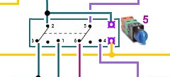
Hello and sorry to resurrect an old thread but thread has been very helpful. Can someone please tell me what the purple contacts (all the way on the right) on the switch are in post 1? Basically I am building the panel shown on the diagram in post # 4 but I'm having trouble understanding the switches. If I understand correctly the switches controlling the heating elements are using 2 N.O contact blocks. 1 that directly controls the relay and the other that directly controls the contactor. The 3 switches that control the 120V outlets only use 1 N.O contact block. Is that correct? If anyone can please let me know if I have that understanding correct or not and what exactly the purple contacts for the switch are in the diagram it would be great.

Thanks
Your understanding is correct. The purple contacts are the connections for the light within the switch. The switches are illuminated units.

Hope this helps.

P-J
 
Thank you so much P-J. That makes perfect sense now. I found some cheaper (non-illuminated) switches on ebay and from the pictures (and my lack of knowledge about 3 position switches) I couldn't figure out those extra contacts. Do you see any reason why these switches couldn't be used for the system you designed that is shown in post #4?

http://www.ebay.com/itm/PBC-SS22PMA...420?pt=LH_DefaultDomain_0&hash=item230948d4fc

They sell extra contact blocks for these switches so for the 2 needed for the elements I would be able to add the additional 2 N.O contacts.

Thanks

Oh, and now that I've finally signed registered on here I can say THANK YOU P-J!. I've read through so many of your posts and it is just amazing how much knowledge you have shared. I certainly wouldn't be doing this build if it wasn't for you. Thanks!
The switch you reference is A-Ok.

I wish you great success in your build.

P-J
 
Back
Top