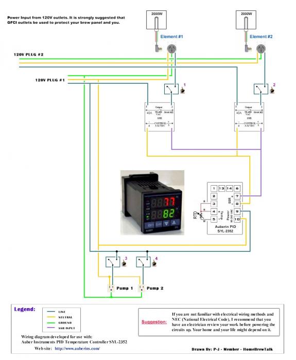
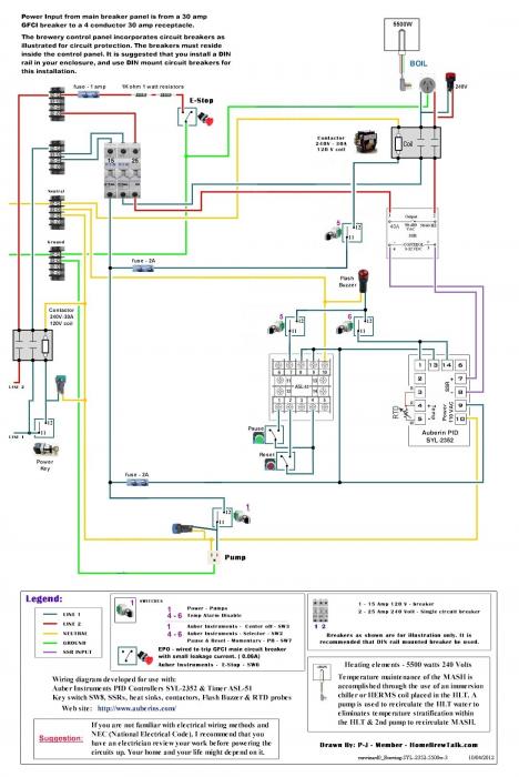
List of PJ Electrical Diagrams

Homebrew Talk - Beer, Wine, Mead, & Cider Brewing Discussion Forum

Help Support Homebrew Talk - Beer, Wine, Mead, & Cider Brewing Discussion Forum:

This site may earn a commission from merchant affiliate links, including eBay, Amazon, and others.
OK I think I'm getting confused with 10/4 and 10/3 wire. Everything I've seen calls for 10/4 cabling from the source. Looking at what lowes sells as 10/3 comes with 4 wires including the ground.

This diagram from ebrew supply shows only 3 wires, not sure where the ground is supposed to go.
http://www.ebrewsupply.com/designs/PID/30a-PID-1-2-1PID-Electric-BIAB.pdf

To be able to put a 120v outlet in for a pump will that lowes 10/3 wire work, and is the ebrewsupply.com diagram correct?

the ground is on all the outlets. Your run the 10/4 into the enclosure and attach the ground to the grounding post. Then connect all the outlet grounds to that as well. Make sense?
 
Hello,

I'm going to be starting a simple build for a single element 120V RIMS unit and I'm trying to find a wiring diagram for this. I noticed in the 1st post there is one that includes an e-stop, which I won't be using, but I need basically the exact thing w/o the e-stop. I'm no electrical genius but I'm great at following diagrams/directions for this kind of stuff.

Any help is greatly appreciated!
Which specific diagram are you referencing? (Link?)

I don't see one for RIMS only. I certainly can draw one for you.
 
Which specific diagram are you referencing? (Link?)

I don't see one for RIMS only. I certainly can draw one for you.

It isn't neccassarily labeled RIMS. It's the 120V single element diagram. I can't link the attachments from the 1st post on here, so here it is attached.

Edit: Oops, attached the wrong one. But this one might a little closer to what I'm attempting. Basically, my plans are for a single element, 3 switches (1 for the pump), single PID/SSR and no e-stop. All on 120V.

Auberin-wiring1-a4-simple-1 (1).jpg
 
Hello,

I'm going to be starting a simple build for a single element 120V RIMS unit and I'm trying to find a wiring diagram for this. I noticed in the 1st post there is one that includes an e-stop, which I won't be using, but I need basically the exact thing w/o the e-stop. I'm no electrical genius but I'm great at following diagrams/directions for this kind of stuff.

Any help is greatly appreciated!

Ok. Here is a diagram that you can use.

As always click on the image to see and save a fullscale diagram for your build.


I hope this helps you.

P-J
 
Thanks so much P-J. That's pretty much what I'm picture it as. As usual, you are very fast with the diagrams. Excuse the "likely" noob questions, but are the contactors completely needed? Could the panel be wired w/o them? Safely....I should add. If the contactors aren't, then would I run the line directly into the box and just break of to how your diagram is wired?
 
Thanks so much P-J. That's pretty much what I'm picture it as. As usual, you are very fast with the diagrams. Excuse the "likely" noob questions, but are the contactors completely needed? Could the panel be wired w/o them? Safely....I should add. If the contactors aren't, then would I run the line directly into the box and just break of to how your diagram is wired?
Contactors??? The last diagram that I posted does not have contactors.

Please explain.

P-J
 
Contactors??? The last diagram that I posted does not have contactors.

Please explain.

P-J

There it is...my noob understanding coming out. I'm referencing the three plates on the left hand side of the diagram.
 
Those are terminal strips:

Here is a reference - 600 VAC Terminal Block

Ok gotcha. That makes much more sense then. I've received some Amazon and HD gift cards, so I'll be having to put the order for the parts in through that channel. But, your explanations have been 1 of the reason I'm making this jump. Looking forward to getting this put together.
 
Ok. Here is a diagram that you can use.

As always click on the image to see and save a fullscale diagram for your build.


I hope this helps you.

P-J

Hi PJ,

I just finished wiring up mine (minus E-stop at this point) and the wiring seems different than the one you attached above. Is the diagram I'm using still valid? When I turned it on the pump worked with the swtich, the pid came on with the switch and when I set the PID to SN-21 for my probe the temp was correct. The SSR lamp was lite and when I turned on my element switch the light pilot lamp came on, regardless of setting the temp over or under the PV. Just wondering why that is and seeing the difference in the diagram wiring to the PID I wonder if my diagram is not correct.

As always, thank you!

Ben

View attachment another RIMS schematic.pdf
 
Hi PJ,

I just finished wiring up mine (minus E-stop at this point) and the wiring seems different than the one you attached above. Is the diagram I'm using still valid? When I turned it on the pump worked with the swtich, the pid came on with the switch and when I set the PID to SN-21 for my probe the temp was correct. The SSR lamp was lite and when I turned on my element switch the light pilot lamp came on, regardless of setting the temp over or under the PV. Just wondering why that is and seeing the difference in the diagram wiring to the PID I wonder if my diagram is not correct.

As always, thank you!

Ben

There is a very basic difference in the diagrams. Yours is for a "Boil" kettle. The one I posted in this thread is for a RIMS system. The RIMS is interlocked due to the very small water volume in the heated chamber.
 
There is a very basic difference in the diagrams. Yours is for a "Boil" kettle. The one I posted in this thread is for a RIMS system. The RIMS is interlocked due to the very small water volume in the heated chamber.

Ah I see. I think I will add that one switch and wire as the RIMS you shown. Should be an easy fix.

Thank you Sir.
 
PJ, your contribution to this site and to the electrically and electronically challenged among us is immeasurable. Thanks so much for all you've given. I am a propane brewer and in the throes of completing my brutus 10 isn setup and the electrical control box is last up. Have you done a diagram for a simple two pump, two PID system system with a main on/off switch? I have LED's for the switches and I have the switches and will add the PID's later when I get the hang of the whole system. Thanks again and I hope you and your family have a great Thanksgiving.
 
PJ, your contribution to this site and to the electrically and electronically challenged among us is immeasurable. Thanks so much for all you've given. I am a propane brewer and in the throes of completing my brutus 10 isn setup and the electrical control box is last up. Have you done a diagram for a simple two pump, two PID system system with a main on/off switch? I have LED's for the switches and I have the switches and will add the PID's later when I get the hang of the whole system. Thanks again and I hope you and your family have a great Thanksgiving.
Tell me a bit more about your desired setup. Which PID are you planning on using? (I hope one from Auber Instruments as I'm familiar with them.)

I'd be happy to draw a diagram for you, but I need a little more info.

P-J
 
Thanks, PJ. Yes, I'm thinking that the Auber SYL 2352 as you usually suggest or 62, not sure what the difference is, really. I've purchased the Electric Brewing supply switches XB2-BD21 simple on-off switches and AD-22 -22DS LED's in various colors (greens for pumps, Red for main on/off, blue for PIDs). I will control the system with main on/off, and each pump will plug into a GFCI socket and I will run a cut-off extension cord into the box to give it all power. I know it may be sacriligious for a propane brewer to be posting on this ebrew site, but your info is the best out there - I'm confident that you know what you're doing.
 
Hi PJ-

Tried to instant message you - went through the diagrams here - and I'm stumped.
I have certainly bitten off more than I can chew - so looking for some of that help - hope you are doing well!

I'm setting up a BCS-462 and it seems like a spider web of connections to coordinate:
7 zones I'd like to 3-way switch (auto/manual) -
1) 3 Vessel - Propane (120V ball valves)
2) Glowfly Circuit
3) 2 pump circuits
4) Instant Hot water (120V ball valve)

Inside I have:
7 SSR, 2 DIN 120V plugs (wifi,bcs), 12V power block, one 20A circuit breaker, an inline e-stop and one power indicator LED (110V) for box power also Driving 3 7-segment LED's, on 12 V.

The switches have 12V LED in them, so Im confused about wiring both manual and auto from BCS (5V) with a 12V LED switch to drive one SSR - is this even logical?

Do you have a system diagram similar to this? Thank you sincerely in advance.
 
I just finished wiring my control panel using the wiring diagram below. One thing I just noticed (and changed in my panel) is that the contractors isn't protected by a fuse in this diagram. It appears that the other diagrams have the fuse, so perhaps this was just forgotten?


Single Element BIAB 30A PID
Auberin-wiring1-a4-5500w-BIAB-30d6.jpg
 
ok so i have read this thread a few times and several others. i fully understand all that is working in this thread but had a twist the only a few i have come across have wanted to try. with this in mind the diagrams and build threads are limited to almost non existent so i was hoping P-J or some other members could help.

basically i am doing BIAB i was about to go electric with PID control as well as timer on my panel using one of diagrams i found here. shown below
biab-single-keggle-61168.html


however after thinking about it long and hard i wanted to incorporate a few other features and needed help with the diagram as well as components.

in addition to the electric control i wanted the ability to run propane also controlled by PID (hopefully the same) and then using a selector switch to chose weather im running electric for indoor winter operations, or gas to switch to propane run for summer operations or when i take the rig to a local brew day with my club.

also if that wasn't enough i wanted to be able to bypass the PID when in electric mode to manually control the boil with a potentiometer knob. I know the pid has manual control, nut just like a few others i like the idea of manual dial to tweak the boil.

so bottom line is a biab system run with the option of electric or propane and Dial boil control in electric.

im hoping someone can shed some light on the wiring diagram here.

thanks

biab single keggle.jpg
 
Hi PJ-

Tried to instant message you - went through the diagrams here - and I'm stumped.
I have certainly bitten off more than I can chew - so looking for some of that help - hope you are doing well!

I'm setting up a BCS-462 and it seems like a spider web of connections to coordinate:
7 zones I'd like to 3-way switch (auto/manual) -
1) 3 Vessel - Propane (120V ball valves)
2) Glowfly Circuit
3) 2 pump circuits
4) Instant Hot water (120V ball valve)

Inside I have:
7 SSR, 2 DIN 120V plugs (wifi,bcs), 12V power block, one 20A circuit breaker, an inline e-stop and one power indicator LED (110V) for box power also Driving 3 7-segment LED's, on 12 V.

The switches have 12V LED in them, so Im confused about wiring both manual and auto from BCS (5V) with a 12V LED switch to drive one SSR - is this even logical?

Do you have a system diagram similar to this? Thank you sincerely in advance.

I just did a lookup on the BCS-462 as I'm not familiar with it. It is a lot more complex than the BCS-460. I've not drawn a diagram for it and it would take a huge effort on my part to make one at this point. (More hours of research and diagramming than I care to invest at this old man's point in life.)

So sorry, I'll have to pass on your request. Wishing you the best.

P-J
 
I just finished wiring my control panel using the wiring diagram below. One thing I just noticed (and changed in my panel) is that the contractors isn't protected by a fuse in this diagram. It appears that the other diagrams have the fuse, so perhaps this was just forgotten?
Sorry. The drawing was made over 2 years ago. Yes, do add a fuse for the contactor pick circuit or just wire it to the pump power feed (10A fused circuit.)

P-J
 
So I was looking over your plans and was wondering if it would be possible to do a 30a 2 5500 2 pump 2 pid. Thanks
 
So I was looking over your plans and was wondering if it would be possible to do a 30a 2 5500 2 pump 2 pid. Thanks
I'm having a problem understanding your plan for your brewery controller.

Using a 30A - 240V feed you can only power a single 5500W element at one time. With that said, a second PID just spends money on something that cannot be used independently.

I have made several diagrams using a single PID. Please explain a little more what you are trying to accomplish and I will make a diagram for you.

P-J
 
Hey P-J

I was thinking that I would need 2 pids since there were 2 elements. I guess after thinking about it I would only need one. Saves money. But is there something I can add to display temps for the mlt? I am hoping to add a Herms as well and might need to monitor that as well.
 
Hey P-J

I was thinking that I would need 2 pids since there were 2 elements. I guess after thinking about it I would only need one. Saves money. But is there something I can add to display temps for the mlt? I am hoping to add a Herms as well and might need to monitor that as well.
With a 240V 30A feed you are really limited in what you can do. It sounds like you want to set up a 3 vessel system - HLT, MLT & BOIL. With that it can be done with a single PID and temp probe. The temp probe would be placed in the HLT. The temp in the MLT would be maintained through the use of a heat exchanger placed in the HLT. The mash temp is maintained by recirculating the mash through the heat exchanger. When it comes time to do the boil the PID is set to manual mode and power for it is regulated with this method (no need for another temp probe).

Here is a diagram that you might find helpful - And as always, click on the image to see and save a full scale diagram that is printable on Tabloid paper (11" x 17"):


I hope this helps you.

P-J
 
Hey pj so Im not getting much luck getting this diagram from any other members so I was hoping you could help me out with my post above. I would much appreciate it .
 
Hey pj so Im not getting much luck getting this diagram from any other members so I was hoping you could help me out with my post above. I would much appreciate it .
 
Hey pj so Im not getting much luck getting this diagram from any other members so I was hoping you could help me out with my post above. I would much appreciate it .
I'm having a hard time identifying the diagram you referenced in your post. Can you post the diagram ID (bottom right hand corner).

P-J
 
P-J, I've looked at a bunch of your drawings. I know I can find something that will work for me. The problem I have is I dont know much about electrical wiring. Would there be a book you would recommend? I think your diagrams are pretty straight forward, but I'd like to have a little background before I get too far in to this. Any recommendations from anyone would be greatly appreciated. I have dome some home wiring (outlets and lights and such). Thank you!
 
P-J, I've looked at a bunch of your drawings. I know I can find something that will work for me. The problem I have is I dont know much about electrical wiring. Would there be a book you would recommend? I think your diagrams are pretty straight forward, but I'd like to have a little background before I get too far in to this. Any recommendations from anyone would be greatly appreciated. I have dome some home wiring (outlets and lights and such). Thank you!
Do a Google search on electrical wiring basics (Click the link) and just do some reading. You will learn a lot in short order.

Hope this helps you.
P-J
 
I have looked through all of the diagrams and I either have missed the one I am looking for or there isn't one. Is there a schematic diagram of Kal's panel exactly (3 Auberin PIDs and 1 Auberin JSL-74 Timer). Thanks in advance for your help in finding this.
 
I have looked through all of the diagrams and I either have missed the one I am looking for or there isn't one. Is there a schematic diagram of Kal's panel exactly (3 Auberin PIDs and 1 Auberin JSL-74 Timer). Thanks in advance for your help in finding this.
That is Kal's panel. Look through his threads and posts to find what you need. Or consider sending him a PM to ask him for what you are needing.

I do not copy or replicate other brewers master wiring plans.

Sorry - .

P-J
 
I've been on his pages which is WHY I am here. No continuity from page to page which makes testing this beast a real challenge. Oh well...:confused:
 
I've been on his pages which is why I am here. No continuity from page to page which makes testing this beast a real challenge. Oh well...:confused:
Sorry. As I said "I do not copy or replicate other brewers master wiring plans."

I suggest that you PM or call him for help.

P-J
 
Hi PJ, I was hoping you might be able to point me in the right direction. A single 2000W rims heater, two pumps, single PID, brew timer with interlocks and LEDs for heating, panel power. Emergency stop too. Thanks, Dave
 
I'm having a hard time identifying the diagram you referenced in your post. Can you post the diagram ID (bottom right hand corner).

P-J

the diagram used is not exactly from you, i took your "mrwizard0_Brewing-SYL-2352-5500w-3" and modified it a bit to my liking. however i wanted to now add PID control for optional propane, and be able to switch between them, possibly add a switch for propane auto and manual for the boil. and finally add a potentiometer as an option under electric control again for my boil.

i know its a lot to ask, and im sure i could use my little knowledge and the various diagrams to figure out what i want but the last thing i want is to hurt myself or my equipment if im wrong.
 
On the diagram you mention a contactor 240v - 30a 120 v coil. I am trying to find it on Auberins and amazon and not sure if I am finding the right thing. Here are the ones I think they could be. I want to make sure I am getting the right one!

Aubreins

Amazon

I was also wondering if there is a cheaper Pid I could get somewhere else like amazon or am I much better buying the authentic one from Auberins?

Thanks!
 
Last edited by a moderator:
Back
Top