can someone help with 120v?

Homebrew Talk - Beer, Wine, Mead, & Cider Brewing Discussion Forum

Help Support Homebrew Talk - Beer, Wine, Mead, & Cider Brewing Discussion Forum:

This site may earn a commission from merchant affiliate links, including eBay, Amazon, and others.

agezzi

Well-Known Member
Joined
May 3, 2010
Messages
106
Reaction score
2
Location
Lafayette,In
Im in the middle of ordering for a 120v e-kettle. what should i get for the element and what is the best way to put it in the kettle and how(10g kettle).As well can anyone help with a wire schematic for a single pid with fuses(and what size) switches for main power and to insure the element is off. i am in a apartment and will use this in conjunction with the stove.I do understand how to wire it, just not sure about the best way and what fuses and switches and lights to get. anything would help. been reading for weeks and cant find what im looking for. Im sure you guys can point me the right way.
 
Is there any other way of going about it without spending a few pretty pennys on tools. Plus having a hard time finding a locking panel mount 120v receptacle or is this needed. I'm lost there is to many different threads and post. As well p-j if ur out there anyway u can help with the wiring for 120v
 
I'd highly recommend checking out the Countertop Brutus 20 thread. He has a 120 system and has lots of things worked out. Also the Simple Brewery.

I'm just finishing up my 120v build right now (2 elements in the kettle, run off of 2 separate circuits), and both threads have been a great help for me.


EDIT: oh, and you don't need a locking panel mount receptacle. You can just use a basic 15a/20a (depending on your build) receptacle. There are lots of ways to go cheaper here. Also search - a lot of people have asked similar questions to yours and P-J has posted a number of simple wiring schematics.
 
I'd start by making sure eKettle with PID control is what you really want for you task.

10 gallon kettle, I'm sure your goal is 5 gallon batches. At 120V, household circuits will limit you to a 2000W element. To be available to run on *any* household circuit, you would need to knock that down to 1500W (run on a 15A circuit). Your kitchen should have 20A (can run the 2000W) circuit(s) but they may not have the right 20A outlets in place for those.

My eKettle is 3000W and it just barely has enough power to get a boil going. You'll be at least 1000W short of that, so you'll need the stove on full-time. Once the stove is going full-time, the attraction of being able to "dial in your boil" using the PID is largely gone - you can just adjust the stove. You're also worrying about protecting the element housing/cord from the stove itself.

I'm all for projects, and would love to help you do this one safely, but I'm wondering if you wouldn't like a 1500W or 2000W heat stick more than a stove-assist ekettle. You could build a nice one with an on/off switch (or even PMW if you want some control - scope out a few recent threads on the topic) for a pretty good price. I loved having one...little extra heat for the mash tun here, little boost for our turkey fryer burner over there.

To answer some of the questions you actually asked-
Fuses aren't really important, but I incorporated a few choice ones sourced from Radio Shack. It's incredible, but they do still sell this stuff. You just put them inline before whatever you're trying to protect.
Fuse Holder
Fuses - Fast acting is what you're looking for if you want to, for example, protect your PID. Check the specs on your particular device, but 0.5A or so should be fine, if it's blowing the fuse in normal operation just bump up in size slightly.

Big spending on tools is also not required. While the punch tools are nice, I'm sure, by being careful and going slowly, we put 5 holes in my stainless steel kettle with a step bit without incident.
 
I just setup my kettle for my 2P-Twent-E brewery (Like the Simple linked above, check my sig line). On this setup I am using silver solder for all my conenctions. I don't have pics up yet, but if you look through the thread in DYI you can see tons. Silver soldering on the element nut (ordered from Derrin at homebrewershardware) is by far the best option I have used or seen so far. It is pro looking and very nice to operate.

All the schematics and stuff can be found in the links in my sig.
 
I agree with dflipse. I built a keggle with 2x 1500w elements, and it does take more time than I'd like to heat/boil water. I did go this route so I can plug it into any two different circuits. And to rant more, I wish I didn't use a keggle for it. I need about 4 gallons of liquid just to cover the elements. totally eliminates it from doing half batches.
 
Subscribed.

[ I'm waiting for a little more detail about the setup required so that I can (might be able to) draw a diagram that could fit the need.

What power is available? (Lots more questions...)
Taps foot waiting....

I think I might have drawn this already (Getting very old sucks!) ]

ROTFLMAO.gif


P-J
 
Why the PID? Are you planning on recirculating back to an MLT? For a simple electric assist kettle, just direct wire a 1650W (for 15A service) or 2000W (20A service) element and use the stove control to regulate your boil.
 
Got a question. I am like i said in an older apartment. I have a 20 amp breaker thats hooked up to the garbage disposal and 3 outlets. one happens to be in the eating area were my kegerator lives. and the other two are in the kitchen. anyway can i hookup a 1500 w element to that breaker with the fridge plugged in? (the mini-fridge is rated at 1.5 amps) thanks for the help guys...and about the pid...
i am building a house that i will be in next year and want to plan ahead. with the pid i should be able to use it down the road when 240v is available.(i have 3 1/2 kegs for down the road.this will b made with my old 10g brew kettle) the thought here was i could still know my temps, so maybe the idea would be to do manual mode at 100% and control with the stove. just a thought. if anyone has a better way of doing things please let me know.
 
As long as you've got a plan to leverage the PID in the future, it makes sense.

The problem with sharing that circuit with the mini fridge is, compressors have a large current requirement at startup. It's possible the breaker will pop when it cycles on.
 
jkarp said:
As long as you've got a plan to leverage the PID in the future, it makes sense.

The problem with sharing that circuit with the mini fridge is, compressors have a large current requirement at startup. It's possible the breaker will pop when it cycles on.

So does that mean when it kicks on it's pulling more then the rated 1.5 amps? If so I will need to find a new spot for the mini-fridge. As well I'm will go with auberin pid. Can I still use buzzer with temp on manual?
 
I don't think it's an issue if you are using a 1500W element, which is only going to draw ~12.5A, if you have a 20A breaker on that circuit.

That is, assuming the wiring in the wall is of the proper gauge.
 
Even at 2000W you only draw ~16 amps. Also breakers are a bit more complicated than just triping if they are over current. There is a curve for how long before a breaker trips based on how much current is drawn. So if it is just barely over you have a little time before a trip.
 
I would be more worried about frying the wiring if it is not up to spec, which can be the case in an older place.

Although in my place even on the 15A breakers all my wire runs are 12ga.
 
So wait could I use a 2000w element? Or should I play it safe and go 1500w. One other thought as well. Could I use a low density 240 at 120. If so watt size would I want to keep in the 1500 range.( if correct they use 1/4 the watts at 120v.) It would b nice not to have to change elements when I move.
 
So wait could I use a 2000w element? Or should I play it safe and go 1500w. One other thought as well. Could I use a low density 240 at 120. If so watt size would I want to keep in the 1500 range.( if correct they use 1/4 the watts at 120v.) It would b nice not to have to change elements when I move.

A 20 amp circuit will handle 2000w. Running a 240v element at 120 will only give 1/4 the wattage, not enough IMO. 1500w is very slow, go at least 2000watts. Run 2 elements at 2000w, 4kw total and you are in business!
 
Ok well I would like a 2000w,but the only breaker I can use is 20 amps. The thing is my mini fridge is on the same breaker. So can I use a 2000w element on a 20 amp breaker with the mini fridge(1.5w)? For now this will just help the boil on stove. Will add another element when I move.
 
Go 2KW. Wost that's going to happen is the breaker will trip when the fridge cycles on. If it does, just unplug it for the brew session.
 
If you are worried about the fridge, unplug it and leave it closed.
The temperature will not drop much in the <2 hours it takes to do an extract batch.
You shouldn't need to do that at all, if the breaker is fairly modern then it is not fast blow like some fuses. It will compensate for the emf required for the inrush current of the fridge.

The old apartment is likely using 14g copper wire. Not to worry though, the only effect you will see at a high current will be a slight voltage drop.
http://www.electrician2.com/calculators/vd_calculator_initial.html
It may be warm to the touch, but the wire will not get hot enough to cause any damage.

Fire occurs when you get a direct short and your breaker fails to trip. Example, try pushing 100A+ through a 14g wire for X amount of time.
 
Thanks guys 2kw it is.
To P-J I found the schematic for the 120 2 element system. If I hook up one now I should b able add another later, right?
The last thing before I start the build. When I move and have a 240 outlet. Can I use that and split it into 2 120 lines in the control box to hook up the other element?

When I start the build I will be sure to take pics along the way. Thank you to everyone for their helping me figure this out.
 
agezzi said:
Thanks guys 2kw it is.
To P-J I found the schematic for the 120 2 element system. If I hook up one now I should b able add another later, right?
The last thing before I start the build. When I move and have a 240 outlet. Can I use that and split it into 2 120 lines in the control box to hook up the other element?

When I start the build I will be sure to take pics along the way. Thank you to everyone for their helping me figure this out.

Sry... To ask. Does the watts matter in adding 120v lights to the control box. Will the ones from radioshack work
 
Are they incandescent lights or LEDs? Whatever you got from Radio Shack should have the specifications on the package, and if it doesn't, take it back and find out the specs.
 
Yes you can split the line on the 240V outlet, ONLY if it has a neutral.
A 4 prong outlet will have 2 hots, 1 ground, 1 neutral. Standard for a new house.
A 3 prong outlet will have 2 hots, 1 ground OR 1 neutral. From experience they are most likely a neutral, but should be a ground.

On the lights, make sure they are capable with the voltage you are using.
The wattage will determine how bright the light is, other than that it doesn't really matter what you use.

Note:
LED is for DC circuits only or in a low voltage AC application. A 24v LED can be used in a 24vac circuit but it will flash at 60hz, this will reduce its life.
 
It is either an incandescent in a neon plastic filter.
Or they are mini neon lights, they require a minimum of 75vac to light up and are not dim-able.
You should be fine either way.
 
Thanks guys 2kw it is.
To P-J I found the schematic for the 120 2 element system. If I hook up one now I should b able add another later, right?
The last thing before I start the build. When I move and have a 240 outlet. Can I use that and split it into 2 120 lines in the control box to hook up the other element?

When I start the build I will be sure to take pics along the way. Thank you to everyone for their helping me figure this out.
I had to do some digging to find the diagram. I was fairly sure I did make one and sure enough:

Click on the image to see a ful scale diagram:


BTW, I made a couple of minor changes to the diagram so that it would be a little easier to setup and use.


Also: Yes, you can do a hookup using a 240V circuit.

P-J
 
It really depends on how far you are from the service breaker.
I use 12g to reduce my voltage drop since I am about 150' from the breaker.

It should be fine if you are <100' away.
Look around your house, a 1200w microwave uses 14-16g and passes UL standards.
You should be fine with 14g.
 
Ok so it's all been ordered. Can anyone tell me what the dimensions of a auber pid(syl-2352) will take pics as it gets going. I decided to use a PVC cap on the end of the element like in the Brutus 20. I bought jb weld,high temp epoxy and liquid electrical tape. Thought was to seal around the pot and element with jb weld, then use the liquid tape over the terminals to the element( stuff works great, my son and I r into rock crawlers(rc) and have used this many time to water proof the electronics) then will fill cap with epoxy and then use more jb weld around the element to attach the cap. Should this work ok, any thoughts
 
mredge73 said:
It really depends on how far you are from the service breaker.
I use 12g to reduce my voltage drop since I am about 150' from the breaker.

It should be fine if you are <100' away.
Look around your house, a 1200w microwave uses 14-16g and passes UL standards.
You should be fine with 14g.

Ok I got 12/3 that will go from wall to control panel. Then got 14/3 for the control panel to the element. And I'm only about 5 feet from my breaker. The panels in the kitchen. So will that work ok and should I use stranded or solid for the inside wiring of the control panel.
 
So will that work ok and should I use stranded or solid for the inside wiring of the control panel.

Yes it will work fine.
Doesn't really matter what you use inside, since it will stay put after you are done. I would use stranded to the element and to the wall.
 
What's the best way to ground the element to the pot. Mine is aluminum unfortunately. Can I solder that some how. Clueless! As well can anyone help with a earlier post of mine(just a few back). Will doing it that way work out. Thanks
 
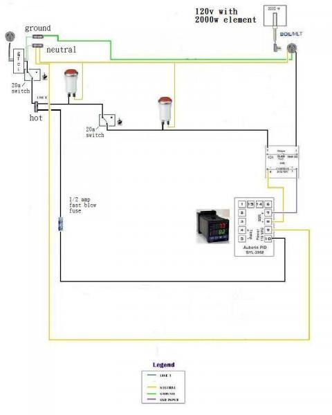
ok starting the kettle today......P-J if ur out there or to anyone that will lend a comment. I played around with P-Js original to come up with this. let me know if this will work and if anything should be changed. thanks everyone for there help,couldnt do it with out you guys....cheers

1 element edit.jpg
 
Assuming those lamps are neon (or any other sub 5mA current bulb), lamps 2 and 3 will always be on at the same time. Voltage is always present through an SSR and they typically leak enough current to light a neon or LED bulb.
 
SSR typical leak current is in the micro amps, so a LED will light but not much else. I use a 1.5W incandescent where your 3rd light is and it works just fine. If your neon stays lit then replace it with a higher wattage bulb.

The diagram is pretty small so I cannot tell what switches you are using, just make sure they are current rated to handle the entire load. Also never fuse the neutral or ground wires, you have a bar on them but I cannot really tell what it is.
 
I'm sorry but your diagram is way to small to be able to see the details of it.
My guess is that you need the 120V version of the 1st link.
 
sry on the diagram,made some changes.it still is a little small,hope you can read it. let me know. i did figure out the buzzer in another thread. thanks to everyone. will try and take pics. starting in the morn did get a chance to tonight.

1 element 120v.jpg
 
SSR typical leak current is in the micro amps, so a LED will light but not much else. I use a 1.5W incandescent where your 3rd light is and it works just fine. If your neon stays lit then replace it with a higher wattage bulb.

While your solution is right, you might want to re-check your spec sheets. Typical SSR leakage is in the 3-5mA range. A heck of a lot higher than you're thinking. Plenty to light neon.
 
Back
Top