5500w ULD element taking too long to heat

Homebrew Talk - Beer, Wine, Mead, & Cider Brewing Discussion Forum

Help Support Homebrew Talk - Beer, Wine, Mead, & Cider Brewing Discussion Forum:

This site may earn a commission from merchant affiliate links, including eBay, Amazon, and others.

Yambor44

Supporting Member
HBT Supporter
Joined
Nov 19, 2008
Messages
2,106
Reaction score
77
Location
Ocala Florida
I have a 5500w uld element in my boil kettle with 7 gallons of water.
PID is a 2352 from Auberin.
RTD is a Pt100 RTD
Sn set to 21.

Set the controller to 165 to simulate strike water for my mash. It has been 50 minutes and it just hit 145.

Any ideas would be greatly appreciated!

8205674877_5f87a5d5f4_b.jpg
 
Do you have a multimeter or other type of gauge that will measure voltage? With the element powered on and your meter set to read Voltage (AC), touch one probe to one of the screws on the element, touch the other probe to the second. It should read between 220-240.
 
My guess is that you're only getting on leg powered, and the other is a neutral or some other return (possibly in a bad way). If your element is rated at 240v and is only getting 120v, then you're only getting 1/4 of the actual power to that element, which would be around the equivelent of a 1300 watt element, which is not enough for a 7 gallon boil.
 
My guess is that you're only getting on leg powered, and the other is a neutral or some other return (possibly in a bad way). If your element is rated at 240v and is only getting 120v, then you're only getting 1/4 of the actual power to that element, which would be around the equivelent of a 1300 watt element, which is not enough for a 7 gallon boil.

I haven't tried to boil yet. Still holding at 165F. Trying to get my PID switched to manual mode to try and boil but not having any luck. Anyone care to chime in on this also.

I do not have a meter here, may be able to find someone to bring one over to check it. Thought trying the manual mode at 100% to check the boil vigorousness might let me know now...if i can get it to switch.
 
Must not be running at full power like you said. Just went 65 more minutes at 100% power, manual mode and the temp only got to 210 so far.

Any idea's what would cause this? Obviously something is wired wrong. Start at the cord and head back from there?
 
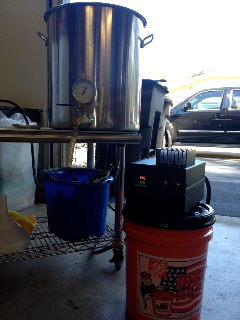
What should be happening:
-You have an element that is supposed to deliver 5500W which is 5.5 kJ/sec.
-The specific heat of water is 4.186 kJ/kg/°C
-The rate of rise should be 4.66/5.5 = 0.84 sec/kg/°C
-You have 7 gal of water which, at room temperature, is about 26.5 kg
-Your temperature rise rate should thus be 0.84*26.5 = 22.26 sec/°C or 0.0449 °C/sec or 2.7 °C/minute.
-To go from 70 to 165 (95°F) should take 95/2.7 = 35 minutes or actually a bit longer as heat is lost though the sides of the pot and surface of the water. If, as has been suggested, you are only getting half (120V) to the heater the time required would be 140 minutes plus.

Another thing that could lengthen the time is if the controller is not sending current to the heater when you think it is.

I assume you have set the controller to do proportional output i.e. there is some cycle time (say it's 100 sec to make this easier) and the algorithm wants 40% heat. It then, in each 100 second cycle, sends the demand signal 40 seconds and turns it off for 60 sec. Most controllers have some indication on their panels to show when they are asking for output. Look at this light. If it isn't on continuously then the controller isn't asking for 100%.

Did you tune the controller? You must do that or it doesn't know how to determine how much power to send to the load in order to regulate without overshoot or droop. Most modern controllers have an autotune feature which makes this once laborious process very easy. Just put in 7 gallons of water and push 'autotune' it may be buried down in some menu but it should be there.

Finally, go to the hardware store and buy two of those rubber light sockets with nothing but wires coming out of them and a couple of 60W or 40W bulbs. Put the bulbs in the sockets and stick one of them into a 120V outlet and note how bright they are. Now connect the pair in series (use a wire nut) and (with the power off) connect the remaining wires across the heater. Now turn the system back on with cold water and a SP of something like 165. Be sure the PV displayed on the controller corresponds closely with the temperature of the water measured with a separate thermometer. Both bulbs should illuminate to full brilliance and should be on all the time until the PV gets within 10 - 20° of the SP. At this point the bulbs will come on once every controller cycle but the time they stay on will be less than the full cycle time. The temperature will smoothly approach the set point without overshooting (provided you did the tuning right).

All this assumes you are using the controller in PID mode which is, I assume, why you would buy a PID controller. If you are using it in differential mode the lights should stay on until the set point is reached and then stay off until PV falls delta below SP.

Forgot to address your request.

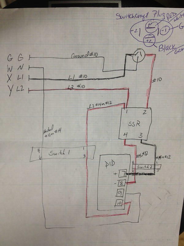
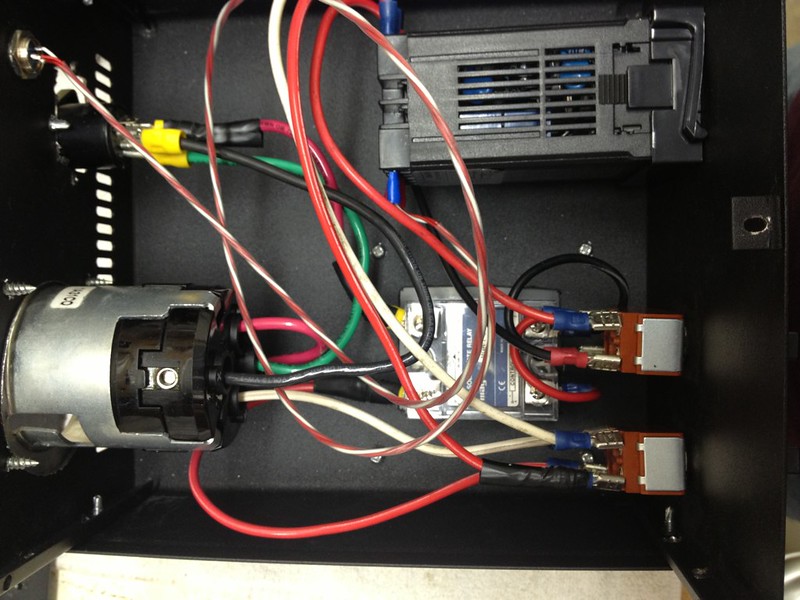
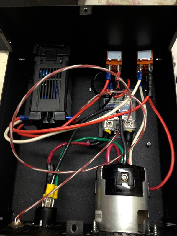
Starting at the place where the juice comes in you should have a red wire, a black wire, a white wire and a bare, green or green with yellow stripe wire. The red and black wires should be connected to an SSR input and its output should be connected to the heater terminals. The green/bare wire should be connected to the chassis. The white wire and either the red or black wire should be connected to the controllers 110V input. The heat demand signal from the controller should be wired to the SSR's gating terminals.

The series pair of light bulbs both glowing at full brilliance confirms that there is 240 V across them without a voltmeter. You ought to be able to buy a cheap multitester at the hardware store for little more than the lightbulbs and sockets. If not you can get one at Radio Shack.

I must say that I get very nervous at the prospect of people who ask questions like this fooling with something that can literally strike them dead if they make a mistake. Any chance you could find someone with some experience to help you?
 
For reference my 4500 watt element did 100 deg f temp increase (55-155) in 20 minutes.

In manual mode you should be able to measure 220v ac at panel output to kettle.
 
ajdelange, no worries about my safety. I know just enough about electricity to leave it to the experts. I do have a friend that will help me.

Are you saying the PID settings may be wrong or need adjusting?

Thanks for your help.

Rob
 
For reference my 4500 watt element did 100 deg f temp increase (55-155) in 20 minutes.

In manual mode you should be able to measure 220v ac at panel output to kettle.

That's more like what I thought it should have been. Actually I was thinking 35 minutes max. Thanks for confirming that.

Thanks.
 
I maintain that your element is getting 120 not 240. Explains a lot of your issues. Until you confirm that your element is getting full 240, there's no possible discussion about what's causing your issue. We need to start eliminating possibilities before seeking to come up with more guesses.
 
ajdelange, no worries about my safety. I know just enough about electricity to leave it to the experts. I do have a friend that will help me.

Glad to hear that. I always had a rule that my guys didn't work on this stuff without another guy present. Of course who was the idiot who put his hand on a live phase? Hint: wasn't one of my guys (fortunately the old one hand in the back pocket rule was being observed and the individual involved was standing on a rubber mat).

Are you saying the PID settings may be wrong or need adjusting?

Yes, they may be. I have no idea how the controller is set up out of the box nor have I noticed people discussing tuning here. I have no familiarity with this particular controller though I did just download and read the manual and found that, among other things, it's not really a PID, but rather fuzzy logic controller, though it will revert to PID under certain circumstances. See the manual section on the autotune function. Perhaps someone with more familiarity with this controller, i.e. one of the many here who actually use it, can comment further.

But the basic principle still applies. When there is a large difference between SP and PV the controller should be sending power to the heater 100% of the time. And, of course, the power should be 240V. If it isn't then something pretty significant is wrong. The heater is wired to 120 (white and red wire for example) or, worse than that, ground and a phase or the SSR is bad. Note that many SSR's are back to back SCR's. If one fails the unit will only deliver half the power it should.
 
I maintain that your element is getting 120 not 240. Explains a lot of your issues. Until you confirm that your element is getting full 240, there's no possible discussion about what's causing your issue. We need to start eliminating possibilities before seeking to come up with more guesses.

That is what I was trying to do, eliminate the possibility that it is a setting issue with the controller (PID). My friend who helps me with this is on vacation this week. I wanted to brew this holiday weekend to get caught up, which is why I was asking for help here, I was hoping it would be something simple.

Soon as I can get someone to check it, I'll let ya know. Thanks again.
 
There are some things you can look at that would give us a clue. The 'OUT' light on the controller should be on continuously. Is it? If it is then it is probably a wiring error or defective SSR. What color are the wires connected to the SSR? If they are not Red and Black or, if different colors, are not wired to the X and Y terminals on the input plug then there is a wiring error. If the controller OUT light isn't on continuously then it isn't 'tuned' right and we can look at that.
 
All the SSRs I've seen only seem to control one leg so it would only have red or black, not both (assuming standard wiring convention was used in his panel)
 
My guess is that you're only getting on leg powered, and the other is a neutral or some other return (possibly in a bad way).

Yeah, that would be really bad if he had a neutral going to one of the 120 legs...yikes.
 
I understand it wouldn't be desirable to the proper heating function of the element if intended to be running on 240V, but why would neutral be "yikes" (which implies hazardous to me), since neutral is normal to a 120V circuit?
 
I maintain that your element is getting 120 not 240. Explains a lot of your issues. Until you confirm that your element is getting full 240, there's no possible discussion about what's causing your issue. We need to start eliminating possibilities before seeking to come up with more guesses.

Gotta love that about internet forums and troubleshooting in general. Let's bounce around all the possibilities of most complex stuff before actually checking the basics. :)
 
I understand it wouldn't be desirable to the proper heating function of the element if intended to be running on 240V, but why would neutral be "yikes" (which implies hazardous to me), since neutral is normal to a 120V circuit?

I was thinking in terms of having one of the hots as a neutral which could cause shorts or if you get a chassy ground (something messed up much more significant than just swapping a neutral for a hot) then you have an electrical shock potential...but, that is not very likely. But, there is nothing wrong running a neutral, that is what 10-4 wire is for stuff like dryers. Most of the time the neutral gets capped and stuffed in the box; but, for things like a dryer outlet the neutral is used...I'd just prefer it is wired to the neutral of the plug and not have it swapped with one of the hots.
 
Here is the basic layout drawn for me. Not showing is the RTD which is bottom left corner of PID.

8209006234_46b3edcdce_c.jpg

The schematic looks OK to me, but I can't tell for sure the inlet and outlet connections by those pictures. Additionally, you have the plugs on the other ends that could be messed up even if the control box is OK.

I think you need to cut to the chase and measure voltage to the element (under load would be best).
 
Now that you mention it, I think the typical 4-pole connector for 120/240V have N and G opposite each other, flanked by the two hot legs.

In those pictures it looks like N and G are adjacent to each other rather than opposite, which could very well be the problem.

Before just swapping around wires the absolute terminal positions have to be determined and then wired accordingly.
 
The diagram looks OK. Assuming that the box is wired to the diagram that means the heater is not getting full voltage. There are 3 ways this could be happening

1. The controller is asking for heat less than 100% of the time
2. The SSR is only conducting on half the cycles
3. The voltage between X and Y is not 240V

1 is easy to check. If the OUT light is on 100% in manual mode and most of the time in auto mode (except when the PV is approching the SP) then the controller is OK.

2 can be verified by temporarily (with the source unplugged) removing the wire from terminal 2 of the SSR and connecting it to terminal 1. Upon plugging back up the rate of rise would increase by a factor of 4 if the SSR were bad and not change if it were good.

3 if the rate of rise does not change then there is less than 240V between X and Y. This would be because the receptacle on the cord that plugs into the box (or that the box plugs into) is not wired correctly or because the wiring of the cable that connects to that receptacle or the wiring of the plug, if any, on the other end of that cable or the wiring of that cable to the box is incorrect.
 
I think jsguitar mostly nailed it. My money is on that inlet connector being wired wrong. Don't believe N and G should be adjacent to each other.
 
To me it looks like the black wire is in "X", therefore the green wire and red wire positions need to be reversed.

However, before simply doing so, please physically ensure the terminal positions.

X = hot (black or red)
Y = hot (red or black)
W = neutral (white)
G = grounding (green)
 
To me it looks like the black wire is in "X", therefore the green wire and red wire positions need to be reversed.

Wouldn't that mean that only N and G are going to the PID though? It shouldn't be working. It might be an error on both sides of the input. I'm thinking the plug is also wired incorrectly.

I was just trying to figure out how the PID could be getting power and the element only getting 120V(if that's the case), hence the suggestion that L2 is actually N and N is actually L2. It seems to me that with the way this is wired that the PID/SSR might be switching neutral, creating the 120V opposite L1 at the element, with the swapped N and L2 lines providing power to the PID.

One thing is for sure, a multimeter is needed here!
 
On the SSR?

No, I mean the RED L2 and the WHITE Neutral coming into the panel could be switched. As said, you really need to check your wiring on the input plug and the wires coming into the panel with a multimeter on the ohm setting to make sure everything is what it's supposed to be. Maybe the outlet too (to be more clear; checking voltage at outlet) if that's been rewired recently. Just don't go swapping any wires until your sure what's what.
 
No, I mean the RED L2 and the WHITE Neutral coming into the panel could be switched. As said, you really need to check your wiring on the input plug and the wires coming into the panel with a multimeter on the ohm setting to make sure everything is what it's supposed to be. Maybe the outlet too (to be more clear; checking voltage at outlet) if that's been rewired recently. Just don't go swapping any wires until your sure what's what.

Okay. The wiring is correct inside the panel box; meaning it matches the diagram.

I will have it checked starting at the wall outlet. Here is a pic of the switch and how the numbers correspond with the diagram as well as On/Off. Don't know if it matters, just thought I'd throw it out there just in case.

8208473799_74569aa3de_b.jpg
 
The diagram shows

L2 - controller - N and L1 - heater - L2

Reversing N and L2 gives

N - controller - L1 and L1 - heater - N

The picture makes it clear that a hot and the neutral have been reversed. N and L2 explains what he is seeing. Reversing N and L1 gives

L2 - controller - L1 and N - heater - L1

and this also explains what he sees provided the controller is capable of operating with 240V primary power.
 
Back
Top