Kal Clone Version X

Homebrew Talk - Beer, Wine, Mead, & Cider Brewing Discussion Forum

Help Support Homebrew Talk - Beer, Wine, Mead, & Cider Brewing Discussion Forum:

This site may earn a commission from merchant affiliate links, including eBay, Amazon, and others.

grupe

Well-Known Member
Joined
Oct 31, 2011
Messages
77
Reaction score
3
Location
Omaha
Here is the start of yet another thread on a clone of Kal’s amazing setup. First off I would like to say that Kal did an amazing job. We can debate his choice of materials all day long, but that really isn’t the point. He did it one way and it turned out amazing. We are going to do it a slightly different way due to our limited monetary resources and we expect to produce something amazing as well.
We knew we wanted to build a tree type setup to reduce the foot print of the set. We also wanted it on wheels so that we could move it around as need. I started off by welding up a frame out of metal that was given to me when purchasing some other stuff off CL. Here is a picture of what it looked like when I was getting started.

302908_10150384605804476_759744475_7947956_1747830853_n.jpg


Here is a picture of the stand it its somewhat final layout. I did end up moving the BV up about 4 inches so that we didn’t have to worry about priming the wort pump.

319592_10150393988924476_759744475_7978136_1077892245_n.jpg


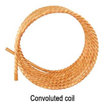
We are using copper for our HERMS coil. We found that bending the tube around a 10 inch OD stove pipe made the job very easy. We had the entire 50’ wrapped up nicely in about 10 minutes.

389491_10150455145699476_759744475_8135114_1942532101_n.jpg


At this point we have received a few of our parts orders. I will update the thread with details on them shortly.
 
Kal,

I am glad to see you are going to keep an eye on this one. So no one has replicated your work vertically? That seems surprising. BTW: You got any ideas where to find the GFCI cord you have in your manual. Either I am searching wrong or the world has run out of them.
 
So no one has replicated your work vertically? That seems surprising.
They may have but I'm not aware of it. I don't find it surprising however: As far as I can tell there are only 2 reasons to go vertical (multi-tier) on brewing setups instead of single tier:

1. To save money as you can build a simpler setup and gravity feed instead of having to use 1 or 2 pumps.
2. To save space.

If you have the space and don't mind having to buy 2 pumps then a single tier setup has many advantages as it is much easier to use as everything is easier to access and safer (no step ladder needed).

BTW: You got any ideas where to find the GFCI cord you have in your manual. Either I am searching wrong or the world has run out of them

I do not - sorry!

Kal
 
We have been working on the control box over the last few days. I would highly suggest buying the punch tools that Kal suggests or at least spending the money to buy good step bits. We are using the $15 ones from Harbor Freight and they are making this a very long and painful process. One thing that in found that helps a lot is drilling one step on the bits and then grinding the lip down on the inside and outside of the box. I have a drill press and that is making the job a lot easier, but it is too small to reach the two middle holes hence the picture of the cover clamped to the work bench. I also made the decision to move the lights and switches for the pumps to the left of the panel. That gives me some room in case I want to add something else in the future (like two flow meters).

380013_10150481657439476_759744475_8239115_16652730_n.jpg


The bottom of the box is done. We didn’t follow Kal’s design here and will show pictures of the final install after we clean and paint the box.

379563_10150481656659476_759744475_8239112_498558775_n.jpg


We took the mounting board out of the control box so we could drill the mount holes with the drill press. Since we were unable to find the cord that Kal references in his build, we went a different route. What we ended up doing is buying a spa panel, take the guts out of it and mounting the GFCI to the mounting board. I had thought about just putting a GFCI in my garage sub panel, but the GFCIs where more expensive than the spa panel. I had also thought about mounting the spa panel next to my sub panel in my garage, but I kind of want to keep this thing portable so the best design I could come up with. We are building in the safety safe start interlock so we ended up getting four relays which are mounted along the bottom. Below the relays is the shunt for the AMP display.

407455_10150481655734476_759744475_8239107_92288751_n.jpg


Over the weekend we got the stuff to build the CFC. I texted my buddy that can solder and he said come on over. About 30 minutes later we ended up with a CFC. I still need to weld in one more cross member as I want it semi securely connected to the main frame.
Some notes:
1. We wound the copper around a paint can. I would highly suggest building the ends and getting the vinyl tube on top of the copper before trying to build a nice looking coil.
2. I decided to mount the CVC below the mash tank for two reasons. The first was we didn’t want I right above the boil vessel where hot steam would be hitting it. The second reason is that we will hardly need any hose to get from the BV to the pump to the CVC. This of course means less wasted beer being left behind in the lines.

394282_10150481653219476_759744475_8239101_613096776_n.jpg


The remaining parts for the weldless fitting are scheduled to show up today. I still have about a hundred things to do, but we are getting closer. I would really like to finish working on the control box tonight, but I guess we will see what the wife has scheduled for me.
 
We got the final parts from MoreBeer to finish the weldless fittings and Proflow to finish the quick connectors. Since we got the parts, it was time to install the HERMS coil. It was a little painful to say the least. Not sure if you can tell, but I put in a “U” loop to hold up the HERMS coil. Basically I took a piece of left over copper, bent it into a “U”, split the ends with a hack saw, slid the slits over the coil and bent them over. I also drill a few holes in the bottom of the “U” loop so that water could drain out of the loop when not in use. I am not sure how important this is, but it seemed like a good idea.

384743_10150485198204476_759744475_8253598_221777089_n.jpg


It was then time to check to make sure the HLT and MLT tanks would hold water. I left the valves open for the HERMS coil open to see if water was leaking into it as it should have ran out if it was leaking.

394678_10150485196959476_759744475_8253597_1605420250_n.jpg


I finally finished the cover and got it painted. The install of the switches, PIDs, Lights, etc went fairly well. As you may notice, the volt meter, timer and alarm reset are missing. We have elected to purchase and install these later. We wouldn’t have purchased the amp meter either, but we needed a template to cut the holes and wanted to mount the shunt.

384845_10150488857049476_759744475_8266851_1170168253_n.jpg


Not really part of the core build, but the Monster Mill showed up. With the help of my kids, we built the base and mounted it to the mill. Not sure if you can see in the picture, but we cut another piece to act as a lip so that mill would not easily slide off the bucket.

405458_10150488505524476_759744475_8265291_645603151_n.jpg
 
Not sure if you can tell, but I put in a “U” loop to hold up the HERMS coil.
This is interesting. Did you find that your copper coil doesn't hold itself up enough without this support? I'm surprised. My coil's stainless which is stiffer but I doubt it matters in terms of holding itself up. (I don't use or feel the need to use anything to hold up the HERMS coil - it's only attached at the kettle walls in 2 spots).

Kal
 
@Kal

Over engineering I guess. I am sure it would have been fine without the support for a very long time, but at the same time we are designing this to be portable if need be. Putting the setup in the back of the pickup and driving a few hours concerned me. At least in my mind right now, I am also sure I would have done the same thing if I would have used SS instead of copper. By no means do I think this should become the "standard" on mounting HERMS coils, but maybe it should be for rigs that are going to get moved.

Thoughts?
 
Nice build so far! You may want to consider orienting your CFC vertically so wort will easily drain out completely rather that leaving some in the lower part of each "loop". It was something I thought about when building mine....
 
Nice build so far! You may want to consider orienting your CFC vertically so wort will easily drain out completely rather that leaving some in the lower part of each "loop". It was something I thought about when building mine....

Excellent suggestion. I will make that change.
 
It's hard to see from the picture, but how long is your CFC? It look like it might only be 10 or 15 feet.
 
I ran down to the post office this afternoon and picked up the SSRs that had arrived from China. Kal does show one picture in his manual on how to mount the SSRs if you aren’t using the big heat sink. I either didn’t understand his design or something as I decided to go a little bit different of a route. First thing I did was cut off the mounting things so that the heat sing looks more like pyramid. Then I marked out the top of the box. The measurements for where I cut can be seen below.

383731_10150495756594476_759744475_8303541_1404328437_n.jpg


The next thing I did was slip the bottom of the heat sink though the hole so that the base was actually under the plate. Then I marked where the bolt holes should go, removed the heat sink, drilled the holes and bolted it all together. Here is one look

383293_10150495757754476_759744475_8303554_212960251_n.jpg


And here is another.

166911_10150495759114476_759744475_8303570_2021164433_n.jpg


I still need to put some caulk around the holes, but this seemed like the best way to mount these to many anyway.

BTW: I think the big heat sink looks super cool and as soon as I can find one, I am replacing these small little things.

Progress is going to slow down a lot at this point as we are waiting for the guys from Chugger to get pumps into stock, my co-partner in this outfit had his appendix out on Monday and I am traveling next week.
 
Is 13 feet to short?

13 feet may be too short. I'm in St Louis and in the heat of the summer the ground water temp can be 70*F. My CFC is 25 feet of 3/8" copper and even with a 50 foot 3/8" pre-chiller (once I'm below 100*F) it takes quite a while. Your mileage my vary, but I'm willing to guess the ground water temps in Omaha are similar to those in St Louis.

Right now I can go from boiling to about 68*F in a single pass - at least for the next couple of months.
 
Depends what kind of coil you have. My CFC's only 12 feet long but the inner coil is convoluted (twisted) on the inside you can get away with a lot less. If you make it yourself odds are it is not convoluted.

convoluted.jpg


The convoluted coil helps create turbulence which creates much better heat transfer.

Some DIY versions of doing this will solder on a wire around and around the inside coil before putting it in the outside coil. That also creates turbulence. Like this:

Chill%20Water%20Turbulence%20(1).JPG


Kal
 
I do not mean to be jerky or anything, but the convoluted coils are not worth the money at all in our case. They will not hurt anything, and look totally badass, and who knows, maybe in the real world they do add something to the equation. But in my experience and theoretically, a convoluted coil will provide no advantage in our situation.

Here is a blog I wrote to detail the subject for those interested. Do I have turbulent flow in my chiller? - Home Brew Forums

Basically, in a 1/2" tube, you need less than 1 gpm (gallon per minute) of flow to produce a fully developed turbulent flow (this is for a straight smooth interior tube, our situation would be lower than this). A standard garden hose puts out well over 5gpm and even my March pump puts out at least 3gpm. In short, you already have fully developed turbulent flow within the tubing without anything additional (wire or twists).

Fully developed turbulent flow is important as it provides the greatest heat transfer from the coolant to the coil.

A more impactful factor is the turbulence of the wort around the outside of the coil. However, in you CFC, you will likely be flowing the wort well above the flow rate needed for fully developed flow.

Again, I am not ragging on anyone's equipment just putting out the fact that flow will be turbulent in your chiller with or without the extra stuff. It may save you a few bones.

Cheers.
 
The last electrical stuff from China arrived yesterday (that is getting installed now) and Chugger got their pumps in yesterday. Pumps are ordered and are on their way. About time to get back to work on this project.
 
It has been slow going as we have been waiting on parts and life has been a little busy as well. Here are the updates. I laid out the back plan of the control board and this is where things are going to go. Looks fairly clean at this point without all the wiring. This was completed on 1-20-2012

166993_10150533786504476_759744475_8427118_847379619_n.jpg


The chugger pumps arrived on 1-23-2013. I have heard they have been banned from the site which is sad, un-American, etc in so many ways. I could write on about this for a long time but it is BS that all the vendors (who make money off reselling march pumps) ran him off.

402510_10150541252074476_759744475_8449939_1199119207_n.jpg


A lot of the vertical build I have seen mount both pumps towards the bottom. I agree with this in a way, but we are only going to mount one at the bottom to reduce the amount of liquid being wasted in the lines and losing heat when going through the lines. Here is a picture of the mounting of the bottom pump. Note the use of expensive John Deere metal which came out of an iron pile at some point.

401396_10150541817159476_759744475_8451339_1138925282_n.jpg


Here is the mounting of the top pump. It is mounted right below the HLT tank to reduce the hose lengths and reduce heat lose. BTW: I am a Kid Rock fan, but I really didn’t mean to frame him in this picture.

397230_10150544192014476_759744475_8456342_542257195_n.jpg


As noted in a previous post, I changed the mounting of the CFC so that it will drain out. I basically took two pieces of angle iron, welded them to the MLT tank mount, notched the angle iron so I could slide zip ties through it and zip tied it down. You can also see in the picture that the temp gauge for the CFC has been mounted.

396712_10150544190964476_759744475_8456340_814724105_n.jpg


On to the control panel. I had to move construction of control panel into the house as the garage gets a little cold this time of year. I set up shop in the dining room until I had the mess from hanging drywall in the basement cleaned up. This of course made the wife happy as random pieces of wire laying on the floor wasn’t her idea of a good time. I locked myself into the basement and finished wiring it around 230 am one morning.

420752_10150555085114476_759744475_8485196_1834187132_n.jpg


Here is a picture of the inside of it. I am going to clean it up after I get it working.

408987_10150555087069476_759744475_8485220_1559351345_n.jpg


Last Saturday morning I lugged the unit out to the garage and plugged it in. I was being careful as I was sure something wouldn’t work correctly. I was correct which of course wasn’t good. After doing some testing I turn the main switch on, but the main relay didn’t engage. After doing some more voltage checking I did some reading on the relays we purchased and determined they were 110 volt DC relays instead of AC relays. Grrr. I ordered the correct relays yesterday and they should be here on tomorrow. I am head back to my parents’ house to make sausage tomorrow night, but plan on swapping the relay on Sunday morning. With any luck we will have the first batch completed before kickoff of the super bowl, but I am not holding my breath.
 
i was a little surprised to see two pumps on a vertical set up... :rockin:
 
PS: I think the moderators ran chugger off not that long ago for promoting product without having a vendor account. Would have been fine without a vendor account if they were just helping with general brewing questions, or how to make it work questions.
 
This tread isn't to debate Chugger's status with HBT, but I know they signed up as a vendor a while back. I am also checking with them and they indicated the mounting of the pump didn't matter. I guess we could test it both ways and see if makes a difference.
 
This tread isn't to debate Chugger's status with HBT, but I know they signed up as a vendor a while back. I am also checking with them and they indicated the mounting of the pump didn't matter. I guess we could test it both ways and see if makes a difference.

Interesting... I would think that it could catch an air pocket in the pump to keep it from priming. I would be intrested if you try it that way to see how hard/ easy it is to prime!
 
I forgot this in my last post, but I would highly suggest getting 3/8 hose instead of ½ hose. The fitting we uses would have easily fit on 3/8 hose, the hose is less expensive and you have less wasted liquid in the hose as it is smaller.

IE: use this http://morebeer.com/view_product/20306/102347/Tubing_-_Silicone_3_8"_ID_-_By_the_Foot
instead of http://morebeer.com/view_product/17608/102347/Tubing_-_Silicone_1_2"_ID_-_By_the_Foot

I also picked up four 10” filter housing for $19 off of eBay the other day. We are only going to use two of the, but at $1.50 a piece I figured I should get some extras.

In addition, I ordered caps for all of the male fittings on the unit. I do a lot more than brew beer in my garage and things tend to get a little dirty. Hopefully this will help keep crap out of the system.

Tonight was the night to switch out the DC relays with AC relays. The switch only took about 45 minutes with two sets of hands. We replaced the main relay with a 50 amp model so we can easily doing a little re-wiring and run both the HLT and BV at the same time. The other three relays we replaced with 40 amp units as they were cheap. We plugged it in and it worked with no issues. We put some water in the HLT tank and it heated up the water nicely. Thursday we plan on running a batch of sugar water though the system to clean out anything that is in the system that could negatively react to our first batch of beer. We are also going to go to Lowes and pickup the parts we need for need to run a two filter system. At this point it just about learning how to run the system and what works and doesn’t. We obviously have a lot of cleanup to do on the panel and frame that that kind of stuff is easy and just requires money. The hard part is was is in front of us: building the perfect beer (if there is such a thing).

418077_10150580083219476_759744475_8557863_841297214_n.jpg
 
I forgot this in my last post, but I would highly suggest getting 3/8 hose instead of ½ hose. The fitting we uses would have easily fit on 3/8 hose, the hose is less expensive and you have less wasted liquid in the hose as it is smaller.
Actually I would make the opposite recommendation and tell people cloning my setup to *NOT* go with 3/8" ID hose. Use 1/2" ID hose. The flow rate/static pressure/restriction is lower and will cause less issues with pumping.

My system was purposely designed to have 1/2" ID throughout the piping and the flow rate I get is fantastic.

I did this after months of reading what others recommended here from trial and error. Everyone seemed to agree that larger (1/2" ID) is better.

You should get little or negligible wasted liquid in the hose. My hose lengths are short (4-6 feet) and I flush the HERMS coil out with water by the way I sparge so that you don't lose any wort. The only place I lose a bit to the hoses is when chilling. Probably a few cups.

Kal
 
Okay. Lets go with Kal's much more scientific reason than mine.
 
Kal,

We ran the system for the first time yesterday and things went really well for our first run. I did have one idea. What if you put a dpdt selector switch off of the SSR outs from the HLT and MLT PIDs. That way when you are mashing, you could control the heating element in the HLT tank from the RTD in the MLT tank. The output side of the switch would continue to go to the HLT SSR. Let me know if you need more info here.
I'm not sure why you'd want to do this.

Kal
 
So you could set the temp on the mlt tank pid and not to have guess at the heat lose through the hoses and pumps.
 
So you could set the temp on the mlt tank pid and not to have guess at the heat lose through the hoses and pumps.
I don't have any heat loss on my system during mashing, or nothing that is measurable. I recirc during mashing to keep the mash temp up. The mash temp exactly matches what I set on the HLT temp. Both temp probes have been calibrated. Both PIDs measure the same. The HLT PID shows the HLT tempature at the output valve. The MLT PID shows the MLT temp at the output valve. See my Brew Day Step by Step for more info and videos on this. One of the videos shows how the temps are exactly equal after they equalize after the first ~5 mins.

Kal
 
What would you say if the garage was at 35 F when we started on Saturday.
 
If you're recirculating constantly you shouldn't be dropping temps at all. Your pot won't be pouring off heat that much.
 
From Michigan here where the outside temp was 6 degrees F on Saturday morning and my garage was about 35 degrees before I turned the heater up to about 50 degrees, there is a much longer lag in the time it takes the temps to equalize. I measure and control the temp at the output of the HLT/HERMS. I have to initially overshoot the target temp by 2 degrees in order to maintain my target temp within the MT at the output initially. It takes a good 20 - 30 minutes to equalize, so I manually adjust the target temp for the first 30 minutes or so to compensate. I have also noticed that if I want to maintain 150 on the mash, and I shoot for 152 on the output of the HERMS, my HLT water heater kicks on when the HLT water is at about 155 and turns off when the HLT water reaches about 160. I imagine flow rate and overall size of HERMS coil are a factor as well. I think the trick is to experiment with your equipment under your specific conditions. I watch the mash temp in 3 different places to see how it reacts. The cold definitely seems to have an impact in keeping a steady and uniform temp throughout the mash and throughout the entire mash process. I am also using A419 controllers, which are probably not as precise or as fast reacting as yours or Kal's.
 
i plan on starting a new thread on this when i get home (with pictures), but i want to discuss our improvements.

1. when we built our panel, we used wire and relays big enough to handle running both elements at the same time. 50 or 60 amp stuff.
2. we switched out the three position element selector switch for a four way switch and wired up a four dpdt relay so we could run both elements
3. we switched out the counter flow chiller for a plate chiller. this reduced our cool down time from 40 minutes to about 12.
4. we added a third pump (yes we have 3 pumps on a 3 tier system) just to pump water from the bv though the plate chiller
5. we added a water manifold so that the house that connects to the house tees into the filters, a hose nozzle to spray out the bv and mlt tank and a line direct to the plate chiller.
6. I have a little garden trailer that we back up to the system to dump the mlt tank. sure is better than caring 30 lbs of wet grain out to the garden.

We are not able to run 4 batches in 12 hours. Not bad to get 60 gallons of beer out of a half barrel system in half a day.
 
Back
Top