My new brew system, a brutus 10 with some nice modifications

Homebrew Talk - Beer, Wine, Mead, & Cider Brewing Discussion Forum

Help Support Homebrew Talk - Beer, Wine, Mead, & Cider Brewing Discussion Forum:

This site may earn a commission from merchant affiliate links, including eBay, Amazon, and others.

jlandin

Well-Known Member
Joined
Nov 10, 2009
Messages
181
Reaction score
19
Location
Mel Bch, FL-US
Edit:

This build is complete! The final cost and parts sheet is at post #80 HERE.

IMG_0176.jpg


Original Post:

This DIY Projects forum is dangerous I tell you!! I had a perfectly good day-tap keg setup, and now I have an 8 keg 4 tap keezer. I had a perfectly good all-grain, single tier, single pump, keggle-on-cajun-cooker-based system, and now I'm building a brutus 10 like system! SWMBO thanks you!

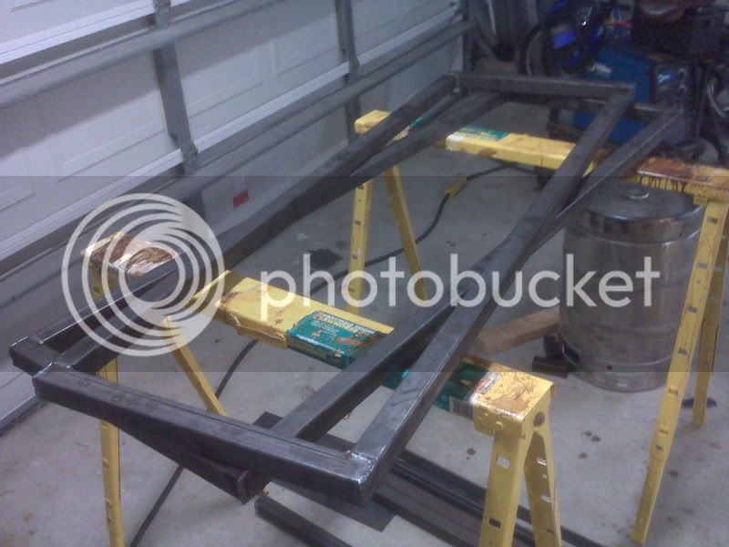
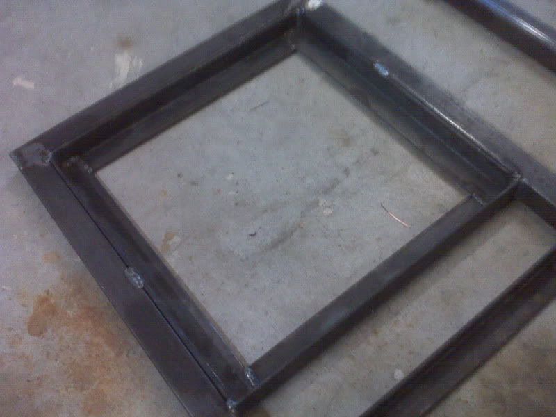
Ok, here goes.. I'm going to try to document this build with as much detail as possible to help others who build a similar system. If I leave something out, and you want clarification or more pictures, let me know and I'll try to accommodate. When I finally finish the build, I will post a parts list with a tally of the cost as I've done before.

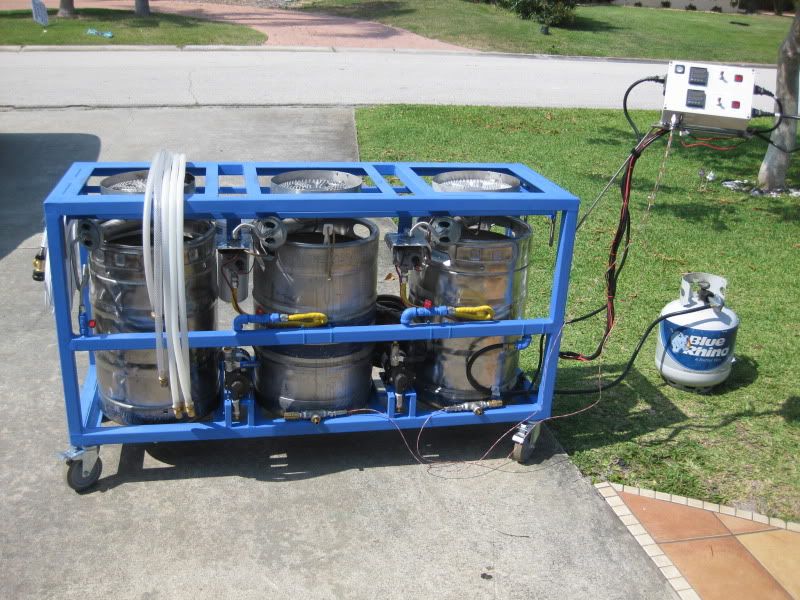
Initially I thought I'd make a brutus 20 for the footprint advantage, but I make several big beers and was a bit scared of the potential limitations of CRDFM. So I decided on the brutus 10 with a few modifications to the original.

Here are some of the key features I was looking for:

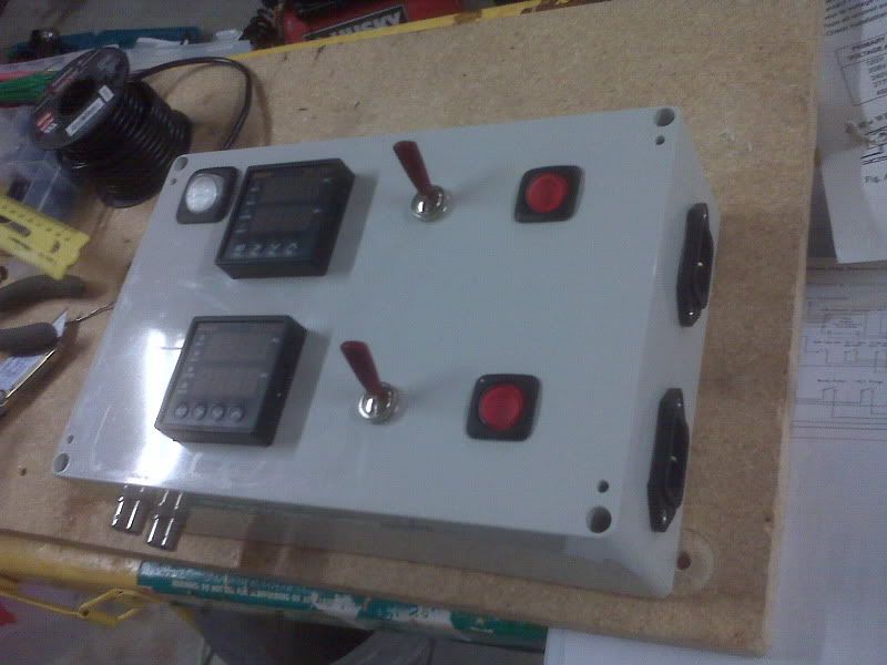
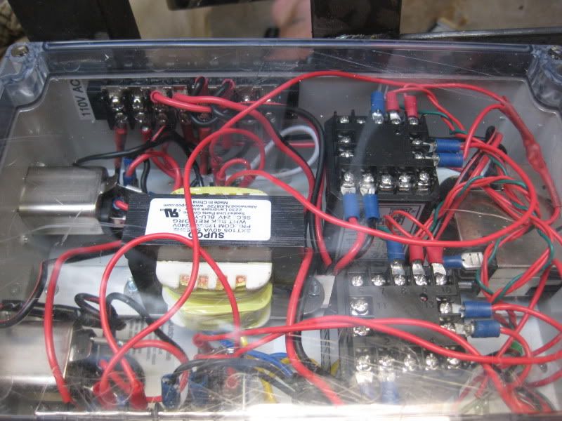
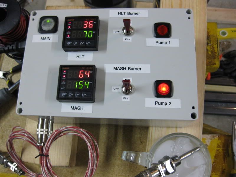
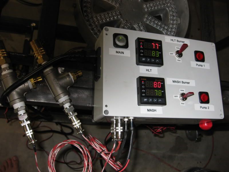
- Automated temp control for HLT and direct-fired MLT.
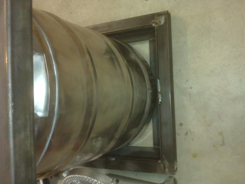
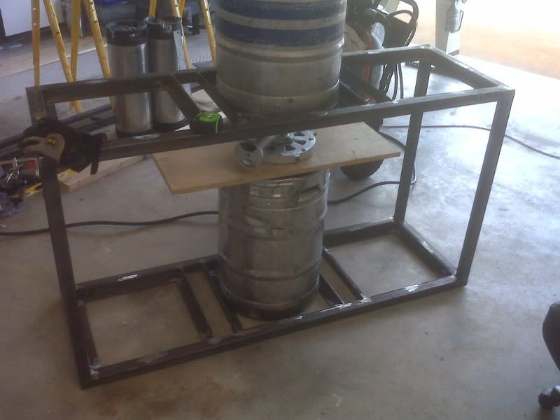
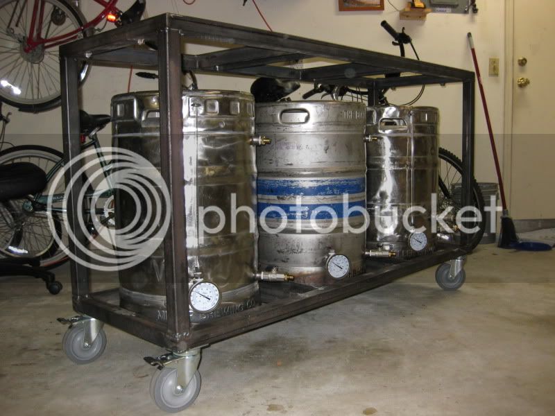
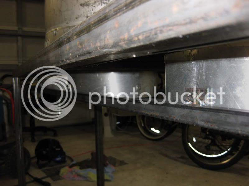
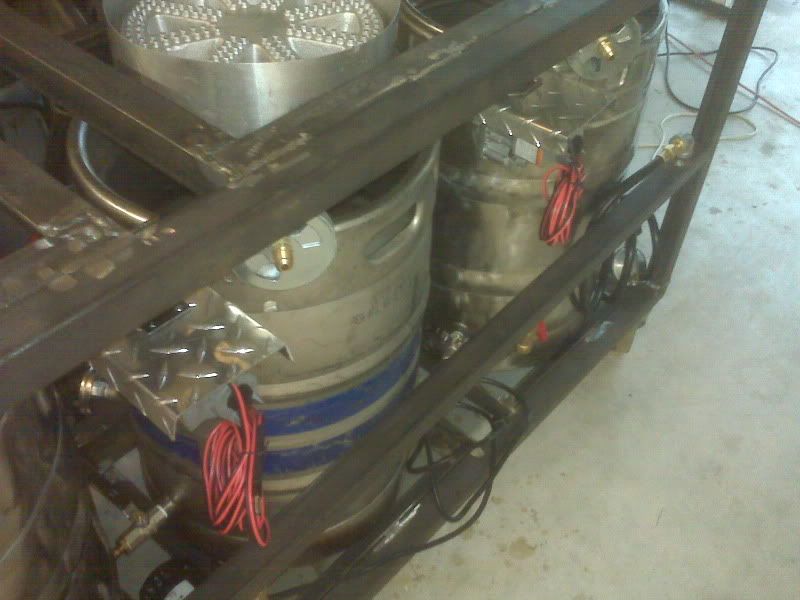
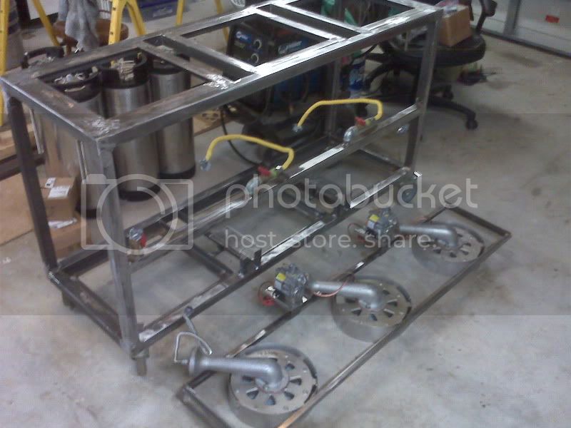
- Ability to store the keggles inside the stand when not in use.
- Nothing extending outside of the rectangular stand frame (plumbing, control arm, etc) when not in use.
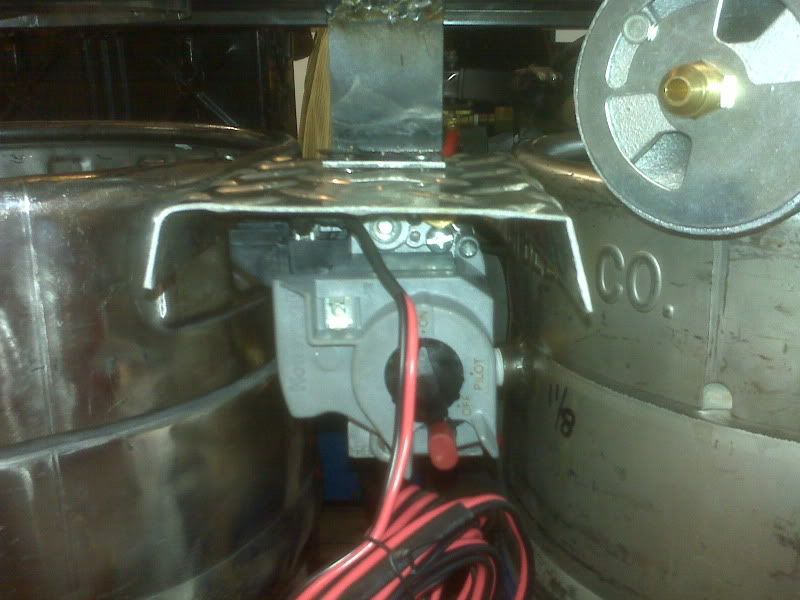
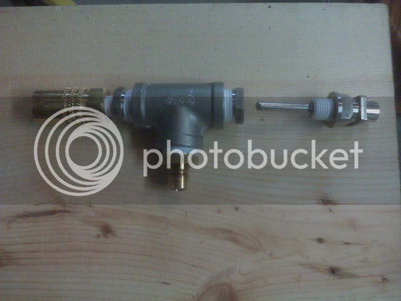
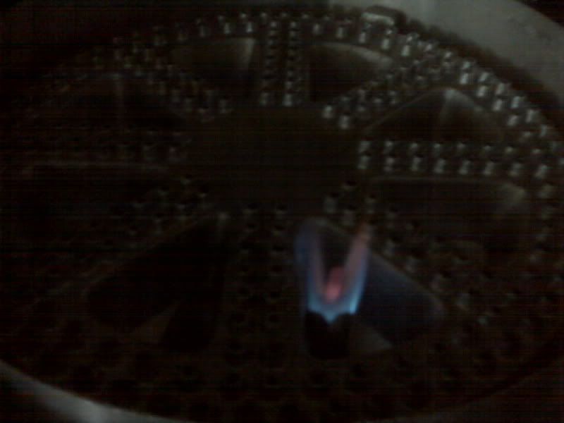
- Thermocouple auto shutoffs for the pilot and burners (thermocouple).
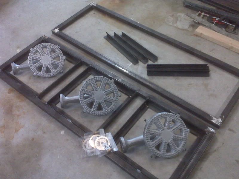
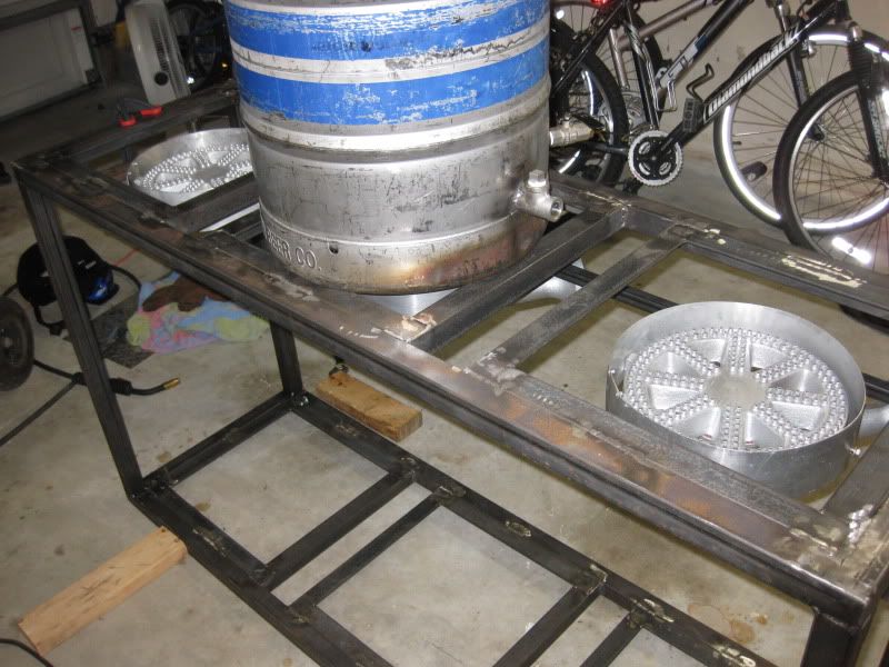
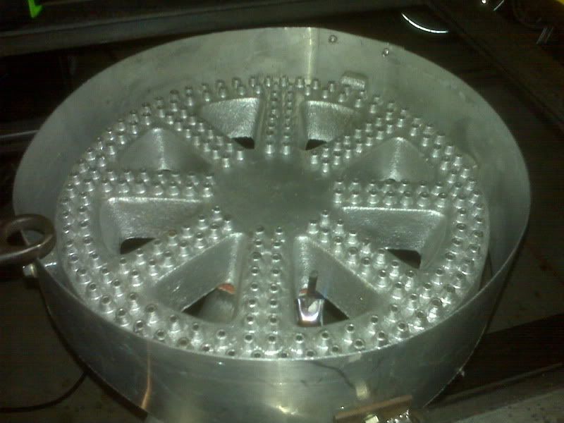
- Three kick a** banjo burners (BG14).
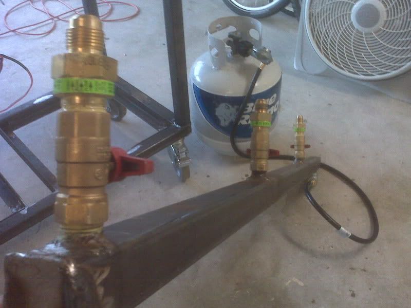
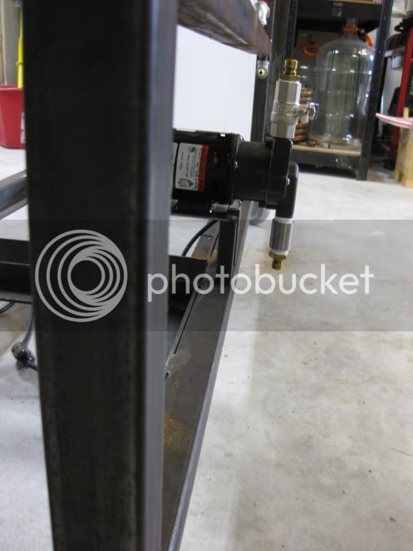
- All low pressure propane.
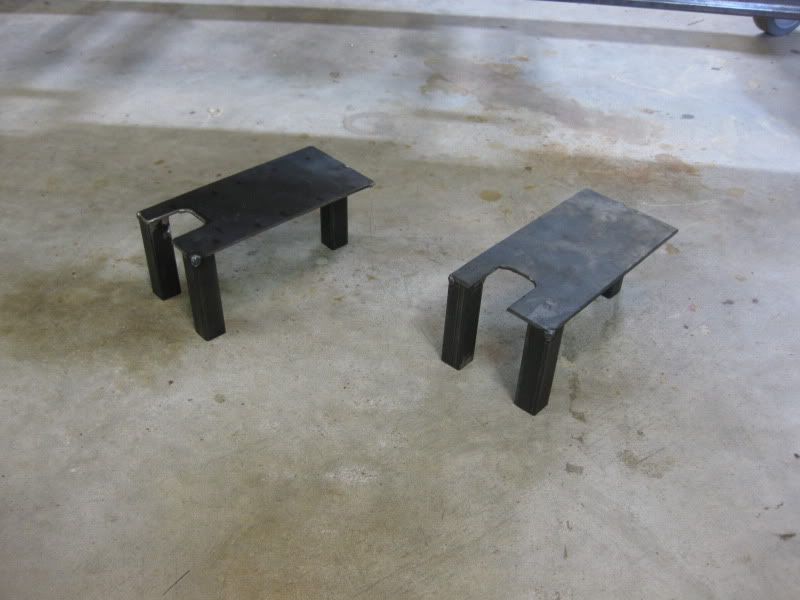
- Adjustable height for all burners.
- Hand-off-auto style switches for burner controls.
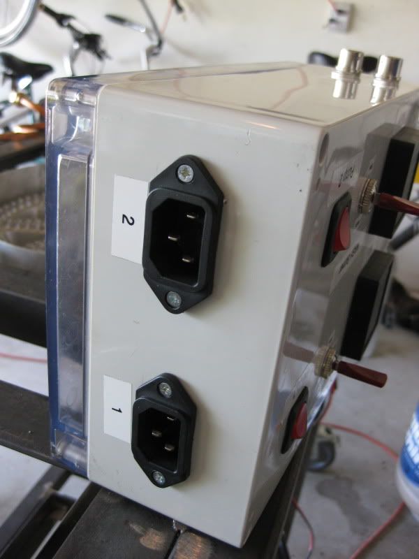
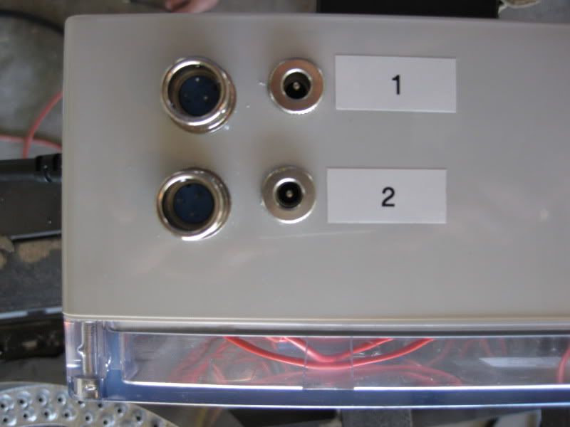
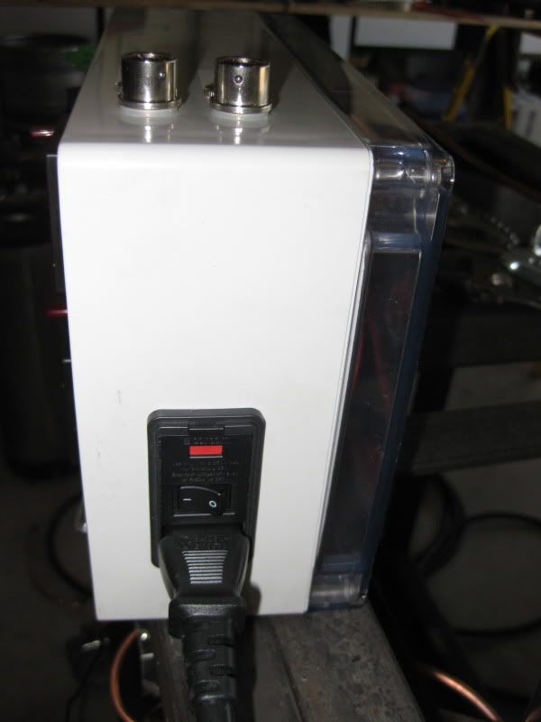
- Detachable control panel so I can bring it in the house when not in use (don't want it to corrode here by the beach).

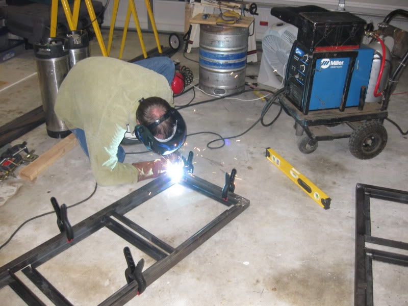
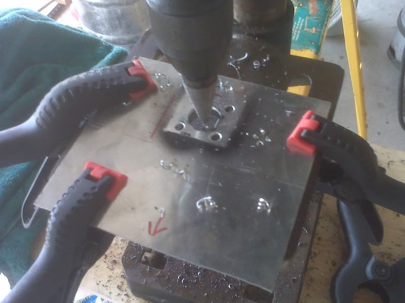
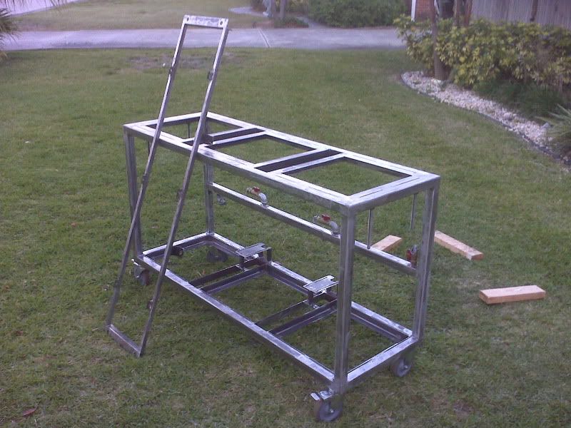
The storage is key, because I want to roll the system under my workbench in the garage when not in use. I've never seen anyone on here do this! I'm generally pretty handy but had never welded before. I didn't even own a welder until this project, but I had been looking for a good excuse to get one. I picked up a good deal on a 230V Miller 175 MIG welder on craigslist and I have really enjoyed that machine!

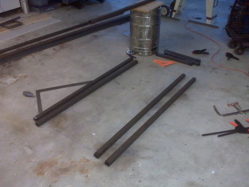
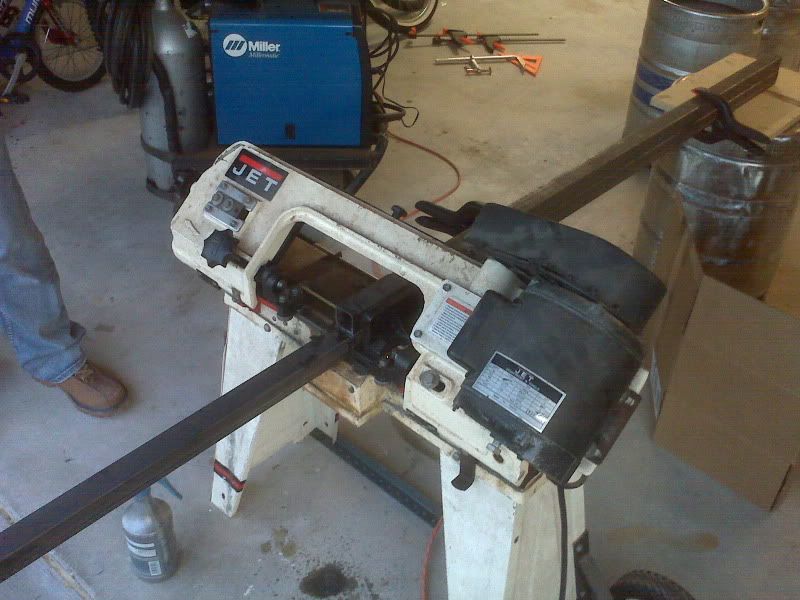
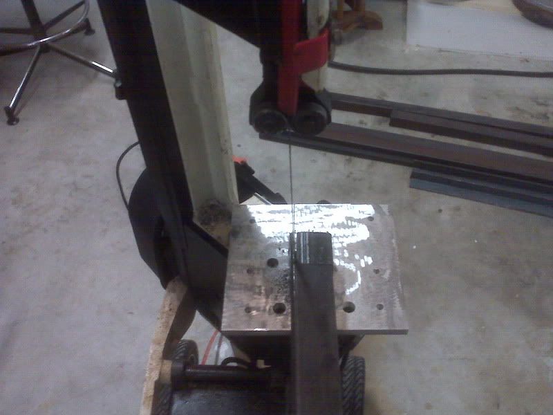
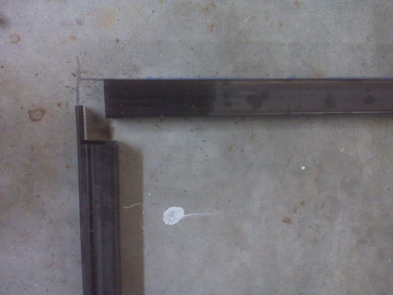
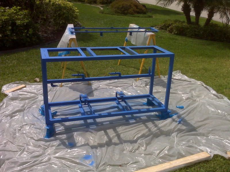
Next up I'll post a timeline of pictures for the progress thus far.

--
Josh
 
Starting the frame... I used 1.5" mild steel square tubing.

IMG00259.jpg

IMG00258.jpg


Notched out the ends:
IMG00260.jpg

IMG00261.jpg


Top and bottom frames:
IMG00262.jpg
 
Height check for storage of kegs inside the stand. I wanted to leave room for the burner height adjustment too.

IMG00274.jpg


Fittings, some McMaster, some ebay, some onlinemetals.com....

IMG_0023.jpg


I sent the kegs off to a welder to be TIG welded. Here they are all finished:

IMG00306.jpg


Boiler (without its thermometer)...

IMG00307.jpg


That looks about right for storage... Added 5" total-lock casters..

IMG_0041.jpg
 
Adjustable burner rack and aluminum wind shields for the burners...

IMG_0037.jpg


IMG_0038.jpg


IMG_0039.jpg


I welded stainless steel nuts to the underside of the frame (here they are just tacked) and screwed in 4 stainless steel threaded rods for adjustment...

IMG_0036.jpg
 
I'm using Honeywell VR8200 furnace valves with integrated pilot for my HLT and MLT. I got the following from Pexsupply the valves, thermocouples, and pilot burners. Both the pilot burners and the honeywell valves come with the LP conversion kits.

Making splash shrouds and brackets for the valves...

IMG00326.jpg


Mounted...

IMG00328.jpg


IMG00329.jpg


IMG_0015.jpg


IMG_0016.jpg
 
Building the control box was fun. I got a plastic box from a friend that was used for some kind of sensors. It has a clear plastic back cover.

I order the following from Auber two PID controllers, two Panel Mount RTD connectors, and two RTD probes. I also picked up some switches from Radioshack and got some power modules from a local electronics store (not radioshack).

Designing the user interface...

IMG00291.jpg


Three way (hand-off-auto) switches in place, adding the pump switches...

IMG00292.jpg


IMG00294.jpg


Pump power outputs without the covers (planning to swap these with female connectors anyway)...

IMG_0014.jpg


RTD Inputs and 24V valve control outputs...

IMG_0012.jpg


Power in...

IMG_0013.jpg


RTD tees (Lonnie Mac style)...

IMG00304.jpg


Here's the box wiring looking in through the clear back...

IMG_0011.jpg


From left to right:
- 2 x output power modules 110V (pumps)
- 110V Terminating block (top)
- 110V to 24V Transformer, 40VA (middle)
- 24V Terminating block (bottom)
- 2 x SYL-2362 PIDs from Auber (in on/off mode)
- Input power module 110V (fused).
- The HOA switches are on either side of the transformer.

Testing...

IMG_0027.jpg


IMG_0005.jpg
 
I made some pump brackets to fit between the keggles (when stored). I'll be milling bolt slots in them to allow the pumps to slide forward during operation. I'll use some wing nuts to tighten them into place. The pumps will slide back and lock in when not in use so that they are not protruding from the face of the stand.

IMG_0111.jpg


Ready for action...

IMG_0112.jpg


Stowed away...

IMG_0113.jpg


IMG_0114.jpg


Here's a look at the whole stand as it is right now...

IMG_0110.jpg
 
Very cool. I will definitely be following the rest of this build.
 
You guys with your well equipped garages really tick me off!!!

Great job though! Like the clear back box to show off your work as well. Controls are always fun, but one of the ways to really show off your project and make it stand out.

Jonathan
 
Thanks everyone!

Next up is finishing the pump mounts, stripping everything down for grinding/cleanup, and then painting.

Hopefully I'll be ready to do a H2O run through on it this weekend to work out any kinks! :D

--
Josh
 
I never thought of notching the steel beams like that, seems like it would make it easier when welding everything up. Also love the storage idea, def gonna have to borrow that one.

-tHeo
 
Thanks everyone for the nice comments. I got some paint on today.

Stripped for paint:

IMG00373.jpg


Going with blue (maybe a racing stripe later):

IMG00376.jpg


--
Josh
 
What paint did you use?.. cuz it going to get pretty effing hot up top :)

I used this header paint from the auto parts store. It's rated for 2000 degrees (Fahrenheit) when cured properly. I'll be curing it in-place, as close to their recommended procedure as I can. Obviously the areas that don't get cured from the burner heat, don't need to handle high temps anyway.

--
Josh
 
I used this header paint from the auto parts store. It's rated for 2000 degrees (Fahrenheit) when cured properly. I'll be curing it in-place, as close to their recommended procedure as I can. Obviously the areas that don't get cured from the burner heat, don't need to handle high temps anyway.
Nice, that's the same paint I used on the wind screen/burner mounts on my rig. I used black. Mine have been through about 6 hours of burner operation and are holding up great! I cured mine in the oven, just because I could.
 
Nice setup. I actually drew up plans to build my stand so I could store my kegs on the bottom. The only thing that concerned me was the height. I might be reaching up and over the keggles. How's the height of the stand for you?
 
It looks like the height of 2 kegs, plus 6 inches for burner mounts plus 3-4 inches for casters.

I'd say

24"+24"+6"+4"=58"

If the brewer is around 6 foot tall they would have no problems, well maybe stirring a mash might be tough, otherwise it seems like an acceptable height.
 
That's damn close! The height from the floor to the top of a mounted keggle is 59". I used 5" casters. ;-)

I'm 6'3" and here is a picture with my arm extended over the mash tun on top of the stand. It's plenty low-enough to stir the mash or watch for hot break. :rockin:

IMG00379.jpg


--
Josh
 
That's damn close! The height from the floor to the top of a mounted keggle is 59". I used 5" casters. ;-)

I'm 6'3" and here is a picture with my arm extended over the mash tun on top of the stand. It's plenty low-enough to stir the mash or watch for hot break. :rockin:

IMG00379.jpg


--
Josh

That might be doable. I'm 5'10". I plan to go electric so I could eliminate 2-3" off the height for the burners and use 4" casters.
 
That might be doable. I'm 5'10". I plan to go electric so I could eliminate 2-3" off the height for the burners and use 4" casters.

Check the pics early in the thread to see where I used angle iron on the inside of lower storage rack. This saves you around 1.5" since the keggles can go in on an angle then be seated for storage.

If you save 1" on the casters, 1.5" on the lower rack, 6" without burners, you're going to be way fine.

--
Josh
 
My casters are 4" tall, the stand is 21" and the kettles are 19" tall. 44" total, and I am 5'11" tall.

I like it because the valves are still within reach and I dont have to stoop, plus is it really easy to get into the kettles.
 
How did you attach the pilot lights to the burners?

Build looks awesome. I'm closing in on finishing my single tier...I think yours has the edge.

I think I'm going to try using the 1/2" pipe going into my Honeywell valve to support it since I didn't build mounting brackets. Hopefully it'll be strong enough.
 
How did you attach the pilot lights to the burners?
Build looks awesome. I'm closing in on finishing my single tier...I think yours has the edge.
I think I'm going to try using the 1/2" pipe going into my Honeywell valve to support it since I didn't build mounting brackets. Hopefully it'll be strong enough.

Thanks Brian! Looking forward to seeing your build thread.

To mount the pilot burners, I first straightened the L-brackets attached to them. I then fed the pilot and thermocouple protrusions up through one of the triangle-sized holes in the banjo. I marked the two bracket holes on the burner underside with a sharpie and drilled them out for two screws (note to self, replace with stainless steel). I did put rectorseal on the screws before installing them just to prevent gas leakage there. Here's a picture:

IMG00380.jpg


I was initially going to do the same thing, black pipe to support my valves. I wanted everything from the valve up to the burner to be rigid, and everything from the valve down to the manifold to be soft. That way the valves move with the burner height adjustment and the pilot/thermocouple lines are not being bent repeatedly. However, I quickly realized that there is no "official" way to go from black pipe NPT to the 3/8" flared orifice fitting with rigid fittings (some on this forum have done workarounds, like brazing the two together, etc but I didn't feel great about doing that). Anyway, the options for me were copper tubing union, or a flexible hose, neither of which would give me the rigid support I wanted. Thus were born, the brackets.

In case you need any, this is a good place for those flex hoses in all sorts of sizes:
http://www.plumbingsupply.com/gasconnectors.html

The brackets mount to the bolt pattern that is already on the valve. Coming out the top of the valve is a brass 1/2" NPT to 3/8" flare elbow. Attaching that to the burner orifice is a 12" x 3/8" flare to 3/8" flare flex hose from PlumbingSupply.

IMG_0015.jpg


Below the valve is the standard yellow flex hose from Lowe's that comes with a 1/2" NPT to 1/2" flare adapter.

IMG_0016.jpg


--
Josh
 
Back
Top