electric brewing question

Homebrew Talk - Beer, Wine, Mead, & Cider Brewing Discussion Forum

Help Support Homebrew Talk - Beer, Wine, Mead, & Cider Brewing Discussion Forum:

This site may earn a commission from merchant affiliate links, including eBay, Amazon, and others.

chainsawbrewing

Well-Known Member
Joined
Feb 12, 2007
Messages
1,185
Reaction score
40
Location
Indianapolis,IN
i've been reading a crap ton on electric brewing over the last week. lot's of information!

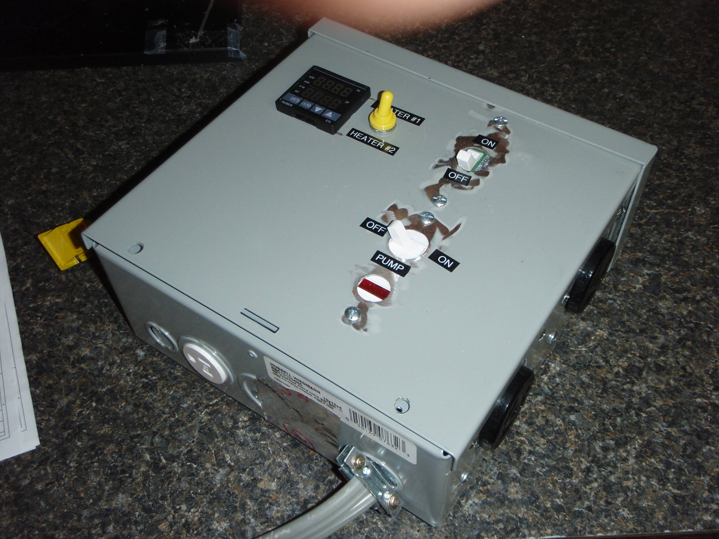
i've seen people build a box, control center if you will, that holds the pid, and the ssr, usually a couple switches to be able to completely cut the power to the elements if needed. also looks like a 120v lead goes from an outlet somewhere else, into this control center/box with two or four gfci plugs, to power up the pid and ssr, and/or a mixing paddle, etc.

also most of the set ups i've seen have a female 220v plug in in the wall somewhere, then from that they have a dryer plug plugged into it, and then the end of that plug also runs into this control center/build box, and they will have another female 220v dryer plug in the side of the box, for plugging in your element. i'm "assuming" that this is just done as a sort of extension, so that you don't have to have a really long wire from your elements to reach over to the wall, and also i would assume it's done so you can have a switch wired to kill the power to the element if needed?

what i can't figure out is, i haven't seen one of these controller boxes with two female 240v outlets on them, however i've seen them set up with a dual element set up, one for the BK and one for the HLT.

are people just plugging in the HLT element, and then when they're ready to boil, turn off the HLT element, unplug it, then plug in the BK element to the same female 240v plug in, turn it on, and boil?

does anyone have a set up with two seperate plug ins, where you can have your HLT element, and BK element both on at the same time, or at least not have to unplug one to plug in the other?

i would assume if someone does have a set up like this, you would have to have two seperate 240v 30a power sources, one for each element, right?
 
[edit] I re-designed and repackaged my controller: see this thread: https://www.homebrewtalk.com/f170/240vac-toolbox-control-panel-pics-184296/

2 240VAC 30A outlets on right side of box.

This should work. It is almost what I have now, except I was stupid and bought thermocouples instead of thermistors. The thermocouples get all screwed up through the switch. I think the thermistors will work fine, though. I can only run 1 element at a time due to my 30A limit, so this is why I used the single PID and switch to select.

Click on pics for bigger version.


The reason you'd have a plug/outlet connection between the element and control panel is if you want to move your vessel out to the driveway to hose it out etc, without having to disconnect hard wiring.
 
passedpawn, thanks a lot. you helped clear up my questions. what's the white female receptical in the bottom of your panel for?

do you have any photos of the inside of your panel also?

your set up looks like what i'd like to emulate, and i'm sure i'll be able to eventually. still doing a lot of reading, and learning right now, but i like the set up of one pid, being able to switch which element is on without having to unplug/plug in cords.


i assume the switch on the left that just says "on/off" kills power completely to the entire box? or does it just kill power to the elements? and also i assume you're using the same 220v lead into the box to also power your pump and pid, ssr, etc? i assume that because i don't see any other leads into the box other than the grey dryer wire coming in from the bottom. i figured you'd need another 120v lead to power the pid, ssr, pump, etc. didn't know one 220v lead would power a 5500w element, and the pump, pid, ssr, etc. all at once.

That 120V receptacle on the bottom would be for his wort pump.

You don't need to feed in separate 120V source if you already have 240V going into the box.

240V service has two 120V hot lines at opposite polarity (giving a total of 240V between them), and it also has a neutral line.

if you tap a connection between one of the hots and the neutral, you get a 120V source.

edit: it's not about how many things you are powering from that main feed, it's about the total amps being drawn. The PID, SSR, and pump draw very little amps (miliamps for the PID and SSR, and maybe 1.5 or 2 amps for the pump.) The only thing really sucking down the juice is the heater element.
 
The other thing to consider also is that two receptacles running an HLT and BK at the same time require two of everything (PIDs, SSRs, Heatsinks, etc.)...with that comes the added power demand, two (2) 5,500 kw elements running at the same time will pull ~46 amps...with the 80% rule, the circuit should be at least 60amps...with a large 60 amp circuit comes more expensive wiring & everything.

For the limited benefit of running both elements at once, it's easier and manageable to just run one at a time. Plug-in whichever element you want to run and go...
 
The other thing to consider also is that two receptacles running an HLT and BK at the same time require two of everything (PIDs, SSRs, Heatsinks, etc.)...

You don't *really* need a PID to control the BK, but yeah.... you end up needing to double a lot of equipment (and get a bigger encolsure... those puppies aren't cheap!)
 
cool. thanks to you too walker.

i would imagine then the main 220v line coming into the project box thingie (forgive my termonology) just goes into a distribution block thing, and then you feed off of that to the two seperate 220v female recepticals, and the 110v female receptical for the pump, with switches in between all of them, and then "hardwire" your pid and ssr to the same distibution block?

distribution block may not be the right term, i'm talking about a thing that has a bunch of screws on it, like you feed it with your main power source, and then have leads off of it to your other "stuff".
 
"Distribution block" is the right term, and yeah... you have the right understanding.

edit: SSRs just sit in between distribution block and 240V receptacles.
 
The other thing to consider also is that two receptacles running an HLT and BK at the same time require two of everything (PIDs, SSRs, Heatsinks, etc.)...with that comes the added power demand, two (2) 5,500 kw elements running at the same time will pull ~46 amps...with the 80% rule, the circuit should be at least 60amps...with a large 60 amp circuit comes more expensive wiring & everything.

For the limited benefit of running both elements at once, it's easier and manageable to just run one at a time. Plug-in whichever element you want to run and go...

thanks, i understand that, i wouldn't see a need to actually run them both at the same time, but still, having two female dryer plug ins, with a switch to power one or the other, but NOT both, you could do away with having to unplug you hlt element, then plug in your BK element, right? you just power the hlt one when you are using it, then when you flip the switch you kill the power to the hlt, then power the element to the BK.
 
passedpawn, thanks a lot. you helped clear up my questions. what's the white female receptical in the bottom of your panel for?

Pump.

do you have any photos of the inside of your panel also?

None that I'd like to share! It's awful. I know better, too, but after getting it working the first time I never went back and straightened it up.

your set up looks like what i'd like to emulate, and i'm sure i'll be able to eventually. still doing a lot of reading, and learning right now, but i like the set up of one pid, being able to switch which element is on without having to unplug/plug in cords.

i assume the switch on the left that just says "on/off" kills power completely to the entire box? or does it just kill power to the elements?

Just the elements. I have another switch like this that disconnects the 240VAC to the outlet. NOTE: USE A 4-PRONG OUTLET!!! GND ALL EXPOSED METAL!!! Don't do it my way... I'm going to fix that as soon as I find a dang ground to tie to... there wasn't one there when I did this, but I'll fix that later.


and also i assume you're using the same 220v lead into the box to also power your pump and pid, ssr, etc? i assume that because i don't see any other leads into the box other than the grey dryer wire coming in from the bottom. i figured you'd need another 120v lead to power the pid, ssr, pump, etc. didn't know one 220v lead would power a 5500w element, and the pump, pid, ssr, etc. all at once.

Yep. 240AC contains two 120 VAC circuits. The voltage (RMS) between the two blacks is 240, but from either black to white (neutral) is 120.

Element = 24A. Pump=1.4A. PID = maybe 0.1A (did not measure).
 
cool thanks everyone. don't worry, i'm not gonna rush into this and fry myself, i know enough to know i have no idea what i'm doing, lol.

i'll probably pay an electricion to run me a lead out of my fuse panel to the proper amperage 220v gfci breaker on it's own seperate box, and then have him run that out to a 220v female dryer receptacle.

i think with some more reading and understanding though i'll be comfortable enough to wire up my box with the pid, ssr, distribution block, etc.
 
thanks, i understand that, i wouldn't see a need to actually run them both at the same time, but still, having two female dryer plug ins, with a switch to power one or the other, but NOT both, you could do away with having to unplug you hlt element, then plug in your BK element, right? you just power the hlt one when you are using it, then when you flip the switch you kill the power to the hlt, then power the element to the BK.

Yeah, you can do it that way for sure. You wouldn't need to double anything other than the receptacles in that situation. The "selection" switch could just control which of the two receptacles the SSR's output was going to.
 
Pump.


None that I'd like to share! It's awful. I know better, too, but after getting it working the first time I never went back and straightened it up.


Just the elements. I have another switch like this that disconnects the 240VAC to the outlet.


Yep. 240AC contains two 120 VAC circuits. The voltage (RMS) between the two blacks is 240, but from either black to white (neutral) is 120.

Element = 24A. Pump=1.4A. PID = maybe 0.1A (did not measure).

i like this idea for the kill switch over by your female dryer plug in.

maybe i'm being silly, but seems to me if you are getting a boilover, or something of the like, that i'd rather have to push a button AWAY from the brew rig, like what you have, versus having to flip a switch on the brew rig.
 
Those dryer plugs can be a pain in the ass to plug in and out.

I have part numbers for everything if you can't read them on my drawing. BTW, those are dual SSRs.

I use a largish heatsink made for 2 SSRs. It's the only one you need if you go with the dual SSRs.
Digikey #CC1702-ND
MFG_HS072.jpg
 
holy cow. $32 for a just a heatsink?

I'm a cheap-skate. :D 
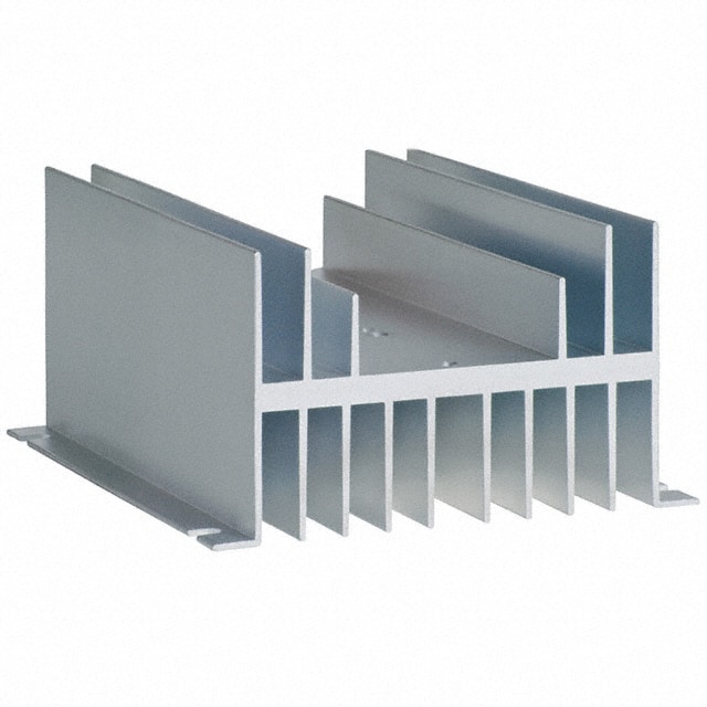
I bought 40A SSRs that included heatsinks for $16 each (free shipping).
 
passedpawn.... your receptacle is three wire? No ground?

Oh yea, that is something else I've been meaning to go back and change. In fact, I think I'll go and remove that picture. I didn't have a ground in the ckt to tie it to (it's just romex coming out of a wall).

The box and kegs should be tied to an earth ground. Absolutely.
 
Those dryer plugs can be a pain in the ass to plug in and out.

I have part numbers for everything if you can't read them on my drawing. BTW, those are dual SSRs.

I use a largish heatsink made for 2 SSRs. It's the only one you need if you go with the dual SSRs.
Digikey #CC1702-ND
MFG_HS072.jpg

yeah, part numbers would be great. did you do a diy write up on your rig?

also, since you can't use both elements at once, why the need for two ssr's?
 
Any of you guys know what it should cost to have an electrician add a dedicated 240V/30A 4-prong outlet in a garage, basically on the other side of the wall from the main breaker (i.e., the breaker is located outside on the side of the garage and the outlet would be inside on the garage wall)?
 
I brew all electric. I have two 220V running off the distro block. Both of those are wired to female receptables mounted near/under the appropriate kettle. Each one is controlled by a PID/Thermo/SSR relay. And I use them both at the same time with no problem. First time I tried it I was expecting the 50Amp breaker to break, but it had no problem running the two 5500 Watt elements at the same time.. Just for fun I tried running the two elements AND the 1500 element (RIMS) AND the pump at the same time.. No problems. FWIW.

Going electric will be worth all your trouble and planning. You won't ever look back.
 
yeah, part numbers would be great.

3PDT Switch (digikey):
http://search.digikey.com/scripts/DkSearch/dksus.dll?lang=en&site=US&WT.z_homepage_link=hp_go_button&KeyWords=S33F-RO&x=23&y=16

Yellow rubber boot for 3PDT (digikey):
http://search.digikey.com/scripts/DkSearch/dksus.dll?vendor=0&keywords=AT402E

DPDT 240V 30A Switch (home depot)
https://cdn.homebrewtalk.com/gallery/data/1/medium/Leviton_30A_240V_DPST_Switch.jpg

Dual SSR (I got my off ebay, cheap) (Allied Electric):
http://www.alliedelec.com/search/productdetail.aspx?SKU=6822397

Internally, I used some terminal blocks to distribute power. Metal box came from Home Depot. PID and temp sensors, Auber. Camco elements came from Rons Hardware, online. The lighted pump switch came from HD also.

I have meant to make decent labels, repaint the box, organize the wiring, but once I got it working I just started brewing with it and never looked back. Time to look back, I guess.
 
No writeup. It's not worthy.

No need for the two SSRs if you don't mind unplugging and plugging the next one in. I was just trying to be clever.

so you can't have two seperate elements hooked up to one ssr?

i thought you would have the two female dryer plug ins on your box both wired to a single ssr. when the hlt element is what you're sending power to, then that plug, and that element is on, and the ssr is controlling that element, and when the switch is on the bk element, then the bk element is on, the ssr is controlling that one.

mind you, if this is a stupid assumption, i have none of these parts in hand, only trying to learn, and only able to learn from photos, and what i can find on here.


basically i understand (i think) that and ssr turns off the power (sort of) to whatever you have wired to it. the pid tells the ssr when to shut off the power to whatever it's plugged into, based on temperature, which you get from some sort of temp. probe hooked up to the pid i think.. you tell the pid that you want your strike water to be 168 degrees, and then your element is on full blast, untill the water reaches 168 degrees, then the ssr "shuts off" the power to that element, untill the water goes below 168 degrees, then the ssr turns the power back on. that's right isn't it?

perhaps i don't need ANY of this stuff....i'm not wanting to build a rims set up, or a herms set up, i don't do any beers that require any changing of the mash temp, and all i do is batch sparge.

basically electric brewing i like because, A. no more buying propane, B. no more loud hum of a banjo burner, C. no worries about actual "fire" in my garage, or melting things like my cooler MLT, no need for heat shields, etc. and i can build a brewstand out of wood if i wanted to, and wouldn't have to worry about dying from propane fumes in the garage in the winter.

i guess if i'm wrong in my assumption about one ssr, one pid, for two seperate elements, i don't really NEED to be able to control/throttle the output of the element on the HLT, right?

if i just had an ON/OFF switch to my HLT, i suppose i could heat my initial strike water, and once i reached the temp. i wanted, simply turn the element OFF, and pump my water to my cooler MLT and then simply turn the element back ON when it's time to heat my sparge water, and the same thing, when it reaches my desired temp, just turn the element back OFF, then after my first runnings, just pump the sparge water from the HLT to the MLT.
then there would be no need for a pid or ssr, right? just a simple dial face thermometer and eyes to look at it and know when to shut off the element. just like now when i heat my strike water using propane. when i reach my temp, i shut off the burner.

but then again, going further, do you really need a pid and/or ssr for the BK either? is there an element that is strong enough to bring up a full 10 gallon boil at full throttle, and you can just walk away without the fear of boilovers, AND is also not so strong that you couldn't do the same for 5 gallon batches?

surely enough people have built super simple electric sanke converted keggles that there's a good, cheaper, happy medium i'm just overlooking here, right?
 
thanks, i understand that, i wouldn't see a need to actually run them both at the same time, but still, having two female dryer plug ins, with a switch to power one or the other, but NOT both, you could do away with having to unplug you hlt element, then plug in your BK element, right? you just power the hlt one when you are using it, then when you flip the switch you kill the power to the hlt, then power the element to the BK.

I believe that this type of 3-way switch, to handle 240v at the needed amperage makes this option cost prohibitive. I don't think there is a cheap alternative out there.
 
I believe that this type of 3-way switch, to handle 240v at the needed amperage makes this option cost prohibitive. I don't think there is a cheap alternative out there.

i apoligize, i have NO idea what this even means, lol.

are you saying a three way switch that has one on, both off, "other one" on that can handle 240v is very expensive?

passedpawn posted the one he uses, http://search.digikey.com/scripts/D..._link=hp_go_button&KeyWords=S33F-RO&x=23&y=16
and it's only $11.59

that doesn't seem very expensive to me, to never have to worry about having to unplug and re-plug in elements all the time.
 
so you can't have two seperate elements hooked up to one ssr? I'm not sure exactly, but keep in mind the SSR has an amperage rating that should be taken into consideration

i thought you would have the two female dryer plug ins on your box both wired to a single ssr. when the hlt element is what you're sending power to, then that plug, and that element is on, and the ssr is controlling that element, and when the switch is on the bk element, then the bk element is on, the ssr is controlling that one.

mind you, if this is a stupid assumption, i have none of these parts in hand, only trying to learn, and only able to learn from photos, and what i can find on here.

basically i understand (i think) that and ssr turns off the power (sort of) to whatever you have wired to it. the pid tells the ssr when to shut off the power to whatever it's plugged into, based on temperature OR MANUAL SETTING IN % POWER, which you get from some sort of temp. probe hooked up to the pid i think.. you tell the pid that you want your strike water to be 168 degrees, and then your element is on full blast, untill the water reaches 168 degrees, then the ssr "shuts off" the power to that element, untill the water goes below 168 degrees, then the ssr turns the power back on. that's right isn't it? Yeah, basically.

perhaps i don't need ANY of this stuff....i'm not wanting to build a rims set up, or a herms set up, i don't do any beers that require any changing of the mash temp, and all i do is batch sparge.

basically electric brewing i like because, A. no more buying propane , B. no more loud hum of a banjo burner, C. no worries about actual "fire" in my garage, or melting things like my cooler MLT, no need for heat shields, etc. and i can build a brewstand out of wood if i wanted to, and wouldn't have to worry about dying from propane fumes in the garage in the winter. (I concur 100%

i guess if i'm wrong in my assumption about one ssr, one pid, for two seperate elements, i don't really NEED to be able to control/throttle the output of the element on the HLT, right?

if i just had an ON/OFF switch to my HLT, i suppose i could heat my initial strike water, and once i reached the temp. i wanted, simply turn the element OFF, and pump my water to my cooler MLT and then simply turn the element back ON when it's time to heat my sparge water, and the same thing, when it reaches my desired temp, just turn the element back OFF, then after my first runnings, just pump the sparge water from the HLT to the MLT.
then there would be no need for a pid or ssr, right? just a simple dial face thermometer and eyes to look at it and know when to shut off the element. just like now when i heat my strike water using propane. when i reach my temp, i shut off the burner. Some PIDs have 'fuzzy logic', an algorithm that allows the PID to adjust/learn how responsive the water in the HLT is, I believe the PID uses this to prevent overshooting temps. You're method may work but won't be as effective or easy

but then again, going further, do you really need a pid and/or ssr for the BK either? is there an element that is strong enough to bring up a full 10 gallon boil at full throttle, and you can just walk away without the fear of boilovers, AND is also not so strong that you couldn't do the same for 5 gallon batches?

surely enough people have built super simple electric sanke converted keggles that there's a good, cheaper, happy medium i'm just overlooking here, right?

If you find it, LET ME KNOW!!!
 
damn illin8, once i think i'm starting to figure some of this stuff out, you have to come in and rain on my parade and confuse me again. :)

cool to know on the pid percentage thing, versus it just shutting off/on like i thought. i would guess that it actually throttling the output, versus shutting it off and on over and over extends the life of everything.


the only thing i'm still having a major hard time grasping is needing a pid and ssr for an element on an HLT. as i said, i don't know jack about any of this, but in my silly brain, it seems to me if i have an element in a keggle, with no "throttle control" on it, so that it's on full blast, it would be similar to what i do now, which is sit the keggle on my banjo burner, and turn it up full blast.

then when the temperature is where i want it, i would just kill the power to the element, and the heat would stop happening, much like when i reach my strike temp now, i just shut off my banjo burner.

are you meaning that when you kill the power to an element, it doesn't just like *POOF* shut off, but it sort of ramps down? like for example, i'm watching my thermometer on my HLT, and it reads 160*, and i kill the power to the element, and by the time i get that water pumped into my MLT it could be up to 170*?
 
SSR is on or off. Period. Element is never "partly" on.

For the BK, you could leave the element on 100%. When I say 100%, I mean time, not power.

However, 2 things to consider here. First, with some brews I cannot stop the boilover with that much power. So, I go 100% until I get to the boil, then back off to 70%. So, 7 seconds on, 3 off, repeat. 70%.

The second point is cost. The electricity does have a real cost. Might as well save $0.30 on your boil.


well damn, i guess i was thinking right originally then, lol.
so the ssr relays the element on and off over and over. it is LITERALLY killing 100% of the power to the element for a period of time. that period of time is based on the % of power you tell the pid to monitor. using your example, 90% power, the element would be on for 9 seconds, off for 1, over and over and over, correct?

when the element is off is it like i described earlier, jut BOOM, it's off right away?

if so, would i be correct again in what i said about not needing to mess with a pid, or ssr for my HLT then? once i hit strike temps, just turn off/unplug the element, and that's it. just like reaching strike temps in my keggle on top of a banjo burner. reach the temp, shut off the burner, pump to the MLT.
 
if so, would i be correct again in what i said about not needing to mess with a pid, or ssr for my HLT then? once i hit strike temps, just turn off/unplug the element, and that's it. just like reaching strike temps in my keggle on top of a banjo burner. reach the temp, shut off the burner, pump to the MLT.

Yeah, you can do this. I think most people were just assuming you were headed towards a HERMS or RIMS system, but if you just want to use electricity to heat things and want to maintain mash temp with a simple insulated cooler, then you have no reason to buy a PID or anything at all.

You would have no need for a PID or electronic temp probe at all. Your boil kettle can be controled by a simple pulse width modulator controlling the SSR. Simple device with a knob that you can turn to set the on/off duty cycle of the element. (You can literally build a modulator yourself for a couple of bucks if you don't mind soldering a few electronic components together.)

No fancy control box needed here.

sweet. this is more along the lines of what i was thinking, i just hadn't heard nor seen of it.

anybody on here done this before, or have any links of examples on how to get a set up like that going? i will still probably build a box of some sort, to house the "dimmer switch" knob and ssr, and the two female 220v plugs for the two heating elements, and a "kill all" switch, and then a three way switch set up for hlt element on, all off, bk element on.
 
i apoligize, i have NO idea what this even means, lol.

are you saying a three way switch that has one on, both off, "other one" on that can handle 240v is very expensive?

passedpawn posted the one he uses, http://search.digikey.com/scripts/D..._link=hp_go_button&KeyWords=S33F-RO&x=23&y=16
and it's only $11.59

that doesn't seem very expensive to me, to never have to worry about having to unplug and re-plug in elements all the time.

That switch has a Contact Rating @ Voltage of 25A @ 125VAC. A three-way switch rated for 30+ amps @ 240v isn't easily come by...I gave up looking. When I initially started to inquire about electric I had the same idea: https://www.homebrewtalk.com/f51/3-pos-240v-switch-120062/

As far as the PID SSR goes, with the manual input you can adjust the time the element is on (at 100% power). So at 50%, it would pulse on for 0.5 seconds at full power and be off for a 0.5 seconds...obviously giving you the ability of dialing down the rigor of the boil.

I had many of the same questions initially as you have, but I think you will find that after all of the research, time and parts, a PID/SSR controlled system isn't really that much more complicated or expensive...especially when you can 'set it and forget it' and do other things to speed up your brew day. Just my $0.02.
 
sweet. this is more along the lines of what i was thinking, i just hadn't heard nor seen of it.

anybody on here done this before, or have any links of examples on how to get a set up like that going? i will still probably build a box of some sort, to house the "dimmer switch" knob and ssr, and the two female 220v plugs for the two heating elements, and a "kill all" switch, and then a three way switch set up for hlt element on, all off, bk element on.

Yeah, you still need a control box. I just meant that it didn't have to be a fancy one. :D

I've built a couple of the pulse width modulators in the past few weeks. Here's a short (and modified) write up with a video I put in another thread recently:

===============================================

Exmaple PWM schematic:

PWM.jpg


The two components in blue (larger capacitor and the potentiometer) are where you can make changes to control the frequency of this thing.

The frequency will be:

1.44/(C * R)

So, in this example, the circuit will have a frequency of

1.44/(0.000020 * 100000) = 0.72Hz

It will go through one timing cycle every 1.38 seconds.

You can use different sized potentiometer and/or capacitor if you want your cycling period to be longer than this. I actually used 33uF caps on mine for a lower frequency of 0.43Hz (one cycle every 2.3 seconds).

By turning the knob on the potentiometer, you can adjust how much time out of that 1.38 seconds the pulse will be ON vs OFF. Turn the knob all the way one direction and the element will basically be on 100% of the time. Turn the knob all the way the other direction and the element will basically be on 0% of the time.

You will need to supply the circuit with a DC voltage source. If you have an old cell phone charger or other old power adapter lying around, you can use that for the DC source.

The end result is that the "dis" (discharge) pin of the 555 timer chip will periodically drain current (as controlled by your knob setting). When the discharge pin is sinking current, you will get a voltage difference between the + and - wires that are marked as "relay control voltage", and the relay will allow your 220V to pass through. When the discharge pin is not sinking current, there will be no voltage drop across the relay control and the relay will not allow the voltage through.
Here's a video of mine packaged up in a small box:


I don't have any pics of the inside of that box, but I can take some if you want to see it. All that's in there is the guys of an old cell phone charger I had in a drawer (I took the plastic case off so that I could slide it into the plastic box) and a small circuit board with the PWM components on it.

The schematic does not show it, but I added a small LED and 1kOhm resistor so that I could get a visual of the duty cycle easily. That part is not necessary, but blinking lights give it a nice geeky factor.

I plan to cut a rough hole in the front of my control box for the potentiometer and LED to be able to pass through and then drill a couple holes so that the face plate of that thing can be put on the front of the control box and the rest of it can sit on the inside of the box.
 
Last edited by a moderator:
If you want a parts list, I can give you the exact components I ordered from mouser.com (you can also buy any switches you need from them, too.)

I think the total price of the components for the PWM came in at about $3 from mouser.com, and another $1.50 or so for the grey plastic box I put it all into (I bought that at Home Depot.)
 
That switch has a Contact Rating @ Voltage of 25A @ 125VAC. A three-way switch rated for 30+ amps @ 240v isn't easily come by...I gave up looking. When I initially started to inquire about electric I had the same idea: https://www.homebrewtalk.com/f51/3-pos-240v-switch-120062/

As far as the PID SSR goes, with the manual input you can adjust the time the element is on (at 100% power). So at 50%, it would pulse on for 0.5 seconds at full power and be off for a 0.5 seconds...obviously giving you the ability of dialing down the rigor of the boil.

I had many of the same questions initially as you have, but I think you will find that after all of the research, time and parts, a PID/SSR controlled system isn't really that much more complicated or expensive...especially when you can 'set it and forget it' and do other things to speed up your brew day. Just my $0.02.


thanks for your input. i appreciate being able to learn from other peoples research, lol.

let me ask this then, in my set up that i'm brainstorming about, let's say i have a single pid, and a single ssr, only for my BK. i really don't think i need either of those for my HLT, since i'm not doing herms, or rims, i just turn on the power to the HLT element, shut it off when i reach my strike and sparge temps.

anyways, back to the BK, with a single pid, and ssr. do you have to have a thermocuple installed, or can you just manually tell the pid to be at full power, then once i reach a boil, manually tell the pid to cut to 80% or 70% or whatever% (learned through experimentation) to maintain a good rolling boil and will that work? or does the pid rely on the thermocuple/actual temperature reading to tell the ssr when to cycle?

lastly, since you couldn't find a three way toggle that worked, i assume in your rig, you have a single female 220v plug in, and you have to unplug your HLT element, and plug in your BK element everytime you brew, right?

You do not need a thermocouple. The temperature of boiling wort is the same regardless of whether you have a nice rolling boil or a violent boil over. Temp monitoring will be of no use to you.

You will just want a PID with the manual mode to set the effective percentage of total element power (in manual mode, the PID does not need or use the temp probe), or the simple PWM I described to set the effective power.


ok. wow, thanks again for all the info, lol. everyone, thanks a lot. i've learned a ton the last couple days from you guys.

so, as far as i'm concerned, i'm done thinking about the HLT side of this equation. not doing herms, or rims, i have ZERO need for throttle control on the HLT element. do you all agree?

on the BK side, i could either have a single pid, and ssr, with no thermocouple, or anything like that, have the pid in manual mode, set to 100% power (zero throttle control), let it get to a boil as fast as possible.
then once i reach a boil, the pid in manual mode, just dial down the power by a set percentage, which will be experimentation at first, but i'll eventually get to "learn" the power of my element, and will know for example 70% power for a 10g batch, 50% power for a 5g batch. no need for any thermocuple or anything in the BK, the manual mode of the pid is kind of like just a fancy dimmer switch for a heating element. do you all agree?


pid and ssr, no thermocuple for more fancy lights, and easier set up/wiring.

PWM for smaller space taken up, but still need an ssr, and a few "other" componets, and to a novice, would be a bit more difficult to wire up, but would be cheaper.

do you all agree?


and lastly, just having one female element plug in on my control box is the cheapest, safest way to go, because of the cost of a three way switch capable of handling the voltage and amps of the elements.
do you all agree?

thanks again.
 
Yeah, I think you got it.

You'll probably never get a consensus on exactly how to build it because everyone does it a little differently. I took a tip from someone on this forum and totally avoided any switch on my control box that would be passing 240V and high amps through it.

Instead, what I bought were heavy duty contactors (basically, mechanical relays) that will pass through the high amp 240V, but are controlled by a low amp 120V signal. The price of the contactor was only about $1 more than a big toggle switch that could handle the 240V and high amps directly. So, for the same price I have the same end result (flip a switch and turn the power to the element on or off), but an added measure of safety since I am touching something carrying less voltage and amps.

The PWM is cheaper than a manual mode PID by a LONG shot, but yes... it does take some time and care to build. I was into the DIY aspect of this as much as I am into the brewing aspect, so it was fun to build the PWM. The $30 or $40 savings it results in was just a bonus.

edit: the PWM is actually not any smaller than a PID, to be honest. A PID is a couple inches square on the face and about 4 inches deep (roughly), and the little plastic box I put the PWM in is pretty close to the same size, just a different orientation.
 

Latest posts

Back
Top