Trying to wrap my head around HERMS powered by BCS-460

Homebrew Talk - Beer, Wine, Mead, & Cider Brewing Discussion Forum

Help Support Homebrew Talk - Beer, Wine, Mead, & Cider Brewing Discussion Forum:

This site may earn a commission from merchant affiliate links, including eBay, Amazon, and others.
Joined
Aug 28, 2011
Messages
13
Reaction score
0
Location
Bakersfield
I need some direction. I dream of an automated HERMS system powered by BCS-460. I need a good dummy guide for building this. Simplicity is what i want, something like this and this. I'm still too confused to ask specific questions. Looking for some good threads to read.

Edit: I want gas powered. Leaning towards Natural Gas, so i dont need to refill propane.
 
There is simple, but then there is also safety to take into account. I use BCS in my setup, but my build was far more elaborate than what your picturing. Granted you can simplify mine a bit from what I built and still stay safe.
 
What are you design goals?
What *exactly* do you mean when you say you want it 'automated'?

Building anything that's automated is considerably more complex than manual. What you do is put all the work in up front when designing/building instead of in the brew day process. To do this however you need to understand the process completely backwards and forwards.

Kal
 
I want the BCS-460 to automatically control mash temp. But manual control of pumps via browser. I want to get away with using one beer pump for now. If thats possible. Im cool with switching hoses around.
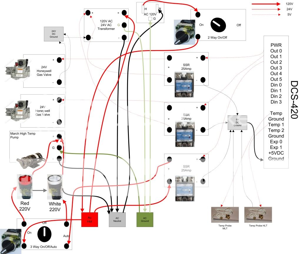
This diagram helps out a bunch. And seems simple enough.
BCS%20460%20Layout.jpg
If I had all the pieces in front of me, i could get it together with supervision of an electrician friend.
What are the advantages of having a manual on/off toggle switch?
And what safety precautions are missing in this diagram?
Heres what i think i need:
BCS-460
(2) 24V Honeywell Gas Valve
(1) Beer Pump
(1)120V AC 24V AC Transformer
(3) SSR 25Amp Relay
(4)Temperature Probes
 
Last edited by a moderator:
It would be advisable for you to have some sort of GFCI for your protection. Because you are for the most part going to be using low voltage, so you cold easily use a 20A or less GFCI. or use a 120V GFCI power cord.

You could add a push button on your control panel wiring it from the +5VDC to a DIN (Discreet input) then you can program the BCS to turn your pump on and off with the button. Or you can add a switch at the pump.

looks like a simple enough design.

Only change to this I would recommend is a switch wired in as auto/manual/off. This way your BCS can control the pump, but at the same time, if your in a jam, the BCS is slow to respond. If you are in an urgent situation, you don't want to be stuck waiting on the BCS. In my setup I went auto-off-on, but I also have the "oh-$h!!" e-stop that can be slammed. Only needed it once so far (when SWMBO was doing the brewing).
 
I think this is what to do, for 2 Way On/Off to Master Power. and a 3 Way On/Off/Auto for the Pump. What else should i think about?
Brewpanel1.jpg
Cleaned up Hot Diagram
Brewpanel1Hot.jpg
 
Initially read is you should be good. I have LEDs on my panel over the switches indicating Pump is on in manual vs pump is under BCS control, which caused me to have to wire the SSR slightly different. But if you skip the LEDs you should be okay.
Any thoughts on add an "oh $h%!" button. Locking mushroom with a NC contact is all you need, wire it on the red side so that when you hit the switch it cuts the power to the gas valves and the pump. Mine cuts the contactors and pumps so all stops, just the BCS stays running.
 
I should add I feel like I'm missing something in the drawing, but won't know what it is until I rack my head with the door of my system.
 
As I suspected, I did have it wired up different. In order for my LEDs and Pumps to cooperate. I wired the DOUT for the pump, as well as the 5V out to either side of the 3 way switch. Therefore, I'm switching the 5v signal and the 110v signal. Only the 110 powers the LED and the 5v and Dout power the pump.
Your wiring plan is good though. The only concern I have is the same I had early, I recommend an e-stop of some kind, whether it is one that trips the GFCI or one that just cuts the power to the items being controlled.
 
Would an E-stop be necessary, if i have a 2 way on/off on the main incoming hot?
I could easily turn a switch and kill the power. Im just not seeing the importance.
Trying to figure out how to add LEDs.
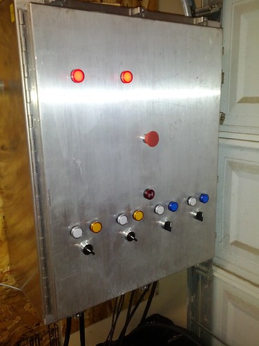
Going to your build in your sig. It looks like you have a light for your on and auto. Which i like a lot. Is that right?
6578700619_c3c32d68da.jpg

And thanks for your help, im starting to get it. I think i will be making a write up for my noob brotheren that cannot wrap their heads around this stuff like me.
 
If you want the LEDs we'll have to rewrite your pump side wiring. I tried to have the LEDs and the pump on the 110v, but wound up with the leds on the 110 and pump control on the 5v. This had to do with trying to power the LEDs and the pump. When I would turn on the pump, the LED would dim, which with my old LEDs, meant they couldn't be seen, so I had to go back and rewire. I also wired it on the 5v because the 22ga wire I used was cheaper than the 16ga wire, which I was running out of. It's worth a try as you have it, run the LEDs in parallel though, so take 2 wires off the switch and have one power the LED and go back to neutral, and the other go to the pump. I will try and sketch something later today for you. My work machine is somewhat limited in capabilities.
 
Prestige
I managed to bet Visio back on my computer. Here was what I took from your plans and mine. The noticable difference really should be the 3 way switch and the pump setup.
There isn't a big avantage to going with the pump only being controlled by the SSR, but there is an asthetic (and therefore wiring) incentive. Its much easier to work in a small box when the wire is small.


*Linked to PDF file
switch-up-close.jpg

backofdoor.jpg
 
Back
Top