Help with 5 amp fuse blowing

Homebrew Talk - Beer, Wine, Mead, & Cider Brewing Discussion Forum

Help Support Homebrew Talk - Beer, Wine, Mead, & Cider Brewing Discussion Forum:

This site may earn a commission from merchant affiliate links, including eBay, Amazon, and others.
the first dwg he posted was, as far as can tell base in the JSL-71 dwg, not the JSL-71A, you can see the first dwg posted match the pinout of the JSL-71 wiring...
 
I am a bit confused about how to wire the selector switches for the two alarms.

In the diagram I have 11 go to 1 on the switch, and 12 in the diagram go to 2 on the switch. This causes the alarm to sound as the timer is counting down.
 
I am also confused about the purpose of the power button. Right now I am able to use everything with the power button off except the element switch. Is this correct?
 
can you post the part number of the power switch? I'm a little confuse on how it is wired... mthe way it is wired it is somekind of useless since you also have a switch for the heating element. The way I see it, to make the switch really turn the whole system on and off, disconnect pin14 at the power switch and splice it to pin 24, this way, when you push the switch on, it will power the system and your heat element power will be sitting at the heat switch until you push this one on too... depress the power switch and it will shut the whole rig down...
 
I checked Auber Instruments site and I had ordered SW11, not SW1 switches. I also programmed the timer so it is sounding the alarm when it finishes countdown, not while it counts down.

Thanks again for your help.
 
The SW1 switch (the correct one in the diagram) is both NO. The SW11 switch (the one I installed) pin 24 is NO, pin 14 NC. Using SW1 will turn power on for everything, then turn everything off when pressed again. I think that is the problem I am having.
 
Actually after checking my order again I ordered the correct switches. Now I am confused why pin 14 stays on, since the diagram for SW1 saws they are both NO.
 
look at pin 14 and 24 again, how would you get power to both? it's going to be, heating element powered OR the rest of the system, quick fis is to disconnect pin 14 and splice it to 24... and you don't even need pin 13....
 
just to make sure turn on power switch and then turn on heat switch... just to make sure fuse can hold it...
 
yeah, already did, worked fine

And thanks for going over this, just saved me $68
 
no prob, i don't know jacksh!t about electric rims, but i can read a wiring diagram!
 
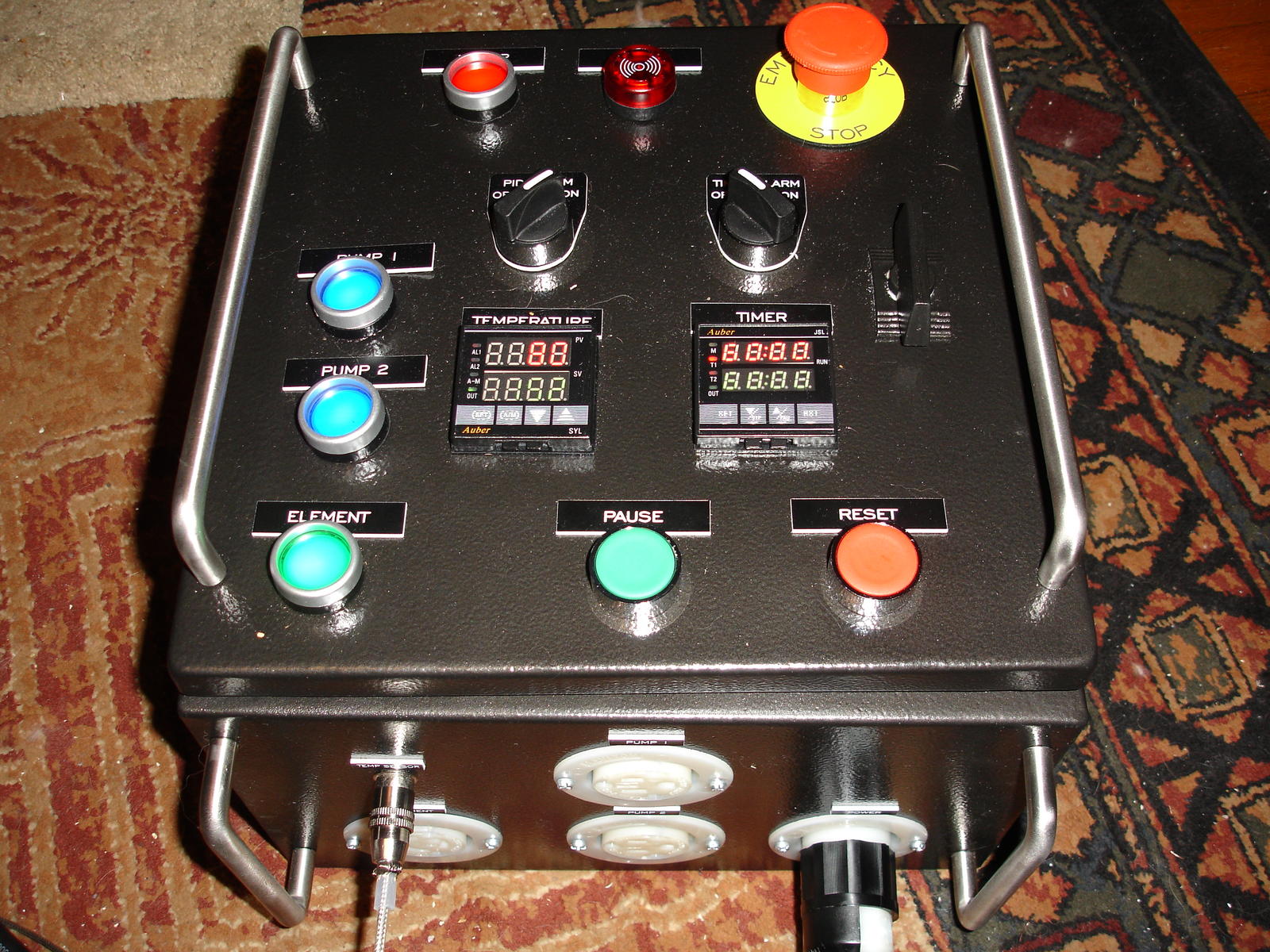
Here is the finished panel. I really liked The Electric Brewery's design. Thanks Kal, P-J and icebob for the help and inspiration to complete this.

DSC01051.jpg
 
Here is the finished panel. I really liked The Electric Brewery's design. Thanks Kal, P-J and icebob for the help and inspiration to complete this.
You are more than welcome. After doing a whole bunch of digging over the initial diagram you posted, I found (and now remember) the design of the first diagram you posted. That diagram was based on a very early version of the Auberin Timer JSL-71 controller. The timer pinout was completely different than what is now available.
Here is the manual for that timer version: http://auberins.com/images/Manual/JSL-71.pdf

So.. The diagram was correct but that particular timer is no longer available. (very serious design changes)

I had been scratching my head over it. Not good for a bald headed old man.

Wishing you well and am proud of you and your intensity on completing your setup. It is fantastic..!

Wishing you the very best.

P-J
 
Back
Top