Controller question

Homebrew Talk - Beer, Wine, Mead, & Cider Brewing Discussion Forum

Help Support Homebrew Talk - Beer, Wine, Mead, & Cider Brewing Discussion Forum:

This site may earn a commission from merchant affiliate links, including eBay, Amazon, and others.
mateomtb,

Thanks.
You do realize that if you intend to power the HLT and Boil at the same time, you need to have at least 100A 240V GFCI protected power available to your controller?

Basically, you would be running 22,000W plus pumps and PIDs.

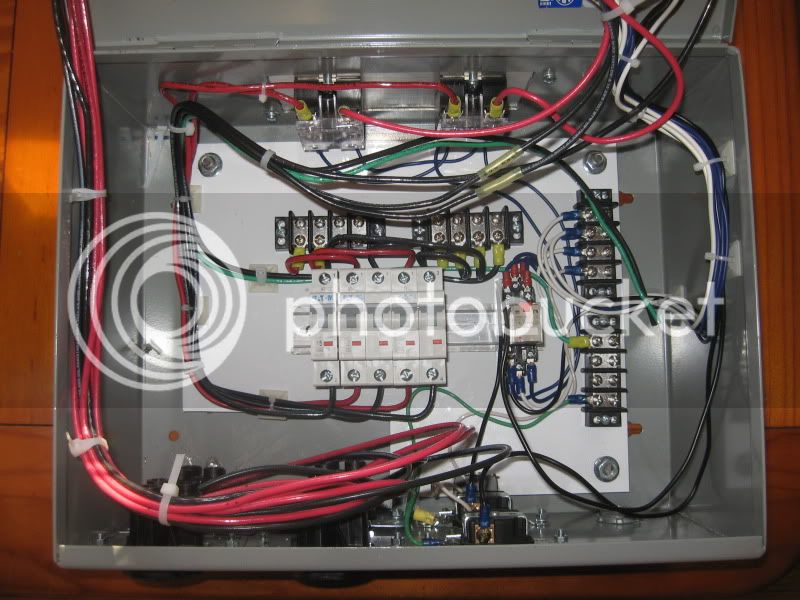
I'm not sure going to a 100A 240V GFCI is the most economical way of doing this. I'm currently working on a set up to run 3 x 5500W elements in both my HLT AND my BK. So I'm pulling 33,000W plus pumps an PIDs (which in my case is a touchsreen computer and a LabJack). This lands me at 137 amps + other crap that adds up to like 10 amps. I figure with a 200 amp service to the building (which shouldn't be too difficult to get) I can split the heating element requirements into 3 x 60 amp GFCI breakers as this is WAY cheaper they trying to buy componenets that can handle 100A+.

All 3 60 amp GFCIs will be run into my panel and power will be distributed from there.

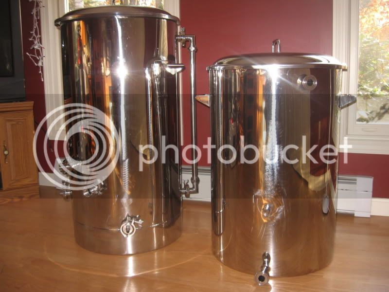
So, Mateomtb, I would think going to 2 x 60 amp GFCIs for your 2 kettles would be a cheaper route. P-J, you seem to have some good knowledge on this stuff. Would you agree or disagree?
 
All 3 60 amp GFCIs will be run into my panel and power will be distributed from there.

So, Mateomtb, I would think going to 2 x 60 amp GFCIs for your 2 kettles would be a cheaper route. J-P, you seem to have some good knowledge on this stuff. Woudl you agree or disagree?

I was thinking the same thing as you, on the surface it makes sense but that's why I'll be having an electrician wire the service for me.

3 elements in the hlt and bk sounds cool. What volume are you planning on heating?
 
P-J, I decided to go with 2 PID's. I was thinking of switching the through switch #1 along with the elements. Do you see any issues with this?
Please help me in understanding the purpose of the second PID. With your currently defined power source, you can only run one set of elements at any given time unless you change your power source to a GFCI protected 100A-240V supply. Without that change, the second PID serves no purpose.

Help me help you. Please.
 
P-J, I was thinking about future expansion. Right now I plan on insulating my MLT and just accepting any heat loss. Future plans may include a RIMS tube but I figured I'd install a second PID now and use it to control the boil kettle.
 
P-J, I was thinking about future expansion. Right now I plan on insulating my MLT and just accepting any heat loss. Future plans may include a RIMS tube but I figured I'd install a second PID now and use it to control the boil kettle.
No problem. Give me a few days to draw it up for you.
 
If all you are trying to do is maintain temps in both kettles you may consider only running one element in each then you would only have 2 on at any time. You would need to have a selector that allows 2BK + 0MLT / 1BK + 1MLT / 0BK + 2MLT to be selected.

Also, there really is no need for a PID in a BK unless you are trying to do double duty with the kettle. If your only use for the kettle is to boil then a simple PWM module with manually controlled duty cycle is much more cost effective. You are going to run the PID in manual mode anyway, which basically turns that expensive piece of hardware into a $9 PWM controller.


my $.02
 
Personally I would use mechanical relays instead of SSR's. Much cheaper and with that much juice going through them, SSR's will tend to get really hot. Plus there's nothing like a good sturdy click to tell you when your elements are kicking on and off.
 
Personally I would use mechanical relays instead of SSR's. Much cheaper and with that much juice going through them, SSR's will tend to get really hot. Plus there's nothing like a good sturdy click to tell you when your elements are kicking on and off.

As much as I agree with this, SSR's along with a controller give a level of temperature control that a mechanical relay cannot provide. The ability to tell the PID or microcontroller to heat to a specific temp is very handy when it comes to mash in temps and allows a "set it and forget it". With the amount of juice and volumes that some of us are talking about, overshooting by 10 degrees for our mash in temps (for example) can be a huge time consumer. 50 gallons of water does not cool down quickly.

Also, anyone doing fine temp control on a recirculating mash will find life much easier if they can program in a target temp.

For the boil kettle, I find that being able to control the level of heat input is super helpful with reducing the risk of boil overs. The on/off control can make things very difficult in the hot break stage of the game. (I guess theres always Fermcap....)

I guess it all comes down to how exact you want to be in your brewing. Sometimes its overkill, but thats what this forum is all about. :)
 
Also, there really is no need for a PID in a BK unless you are trying to do double duty with the kettle. If your only use for the kettle is to boil then a simple PWM module with manually controlled duty cycle is much more cost effective. You are going to run the PID in manual mode anyway, which basically turns that expensive piece of hardware into a $9 PWM controller.

This is a good point. I know when I had a HERMS I was using my BK to heat strike water, while using my HLT, which had my HERMS coil in it, to set my mash temp for recirc. For example, I would put 8 gallons (strike volume, dependent on grain bill) of water into my BK, heat it to around 161 for a target mash temp of 152. I would then set my HLT to 154 so that my HERMS coil was at the correct temp as soon as I began to recirc to maintain my 152 mash temp.

But you are correct. If not using it in this manner (or for some other reason)a PWM is a much simpler solution.
 
SSR's and mechanical relays serve the exact same purpose. The difference is how the switch works. A SSR is essentially a giant transistor so there is inherent resistance to the flow of current hence the heat. Where as a mechanical relay is just an automated light switch and does not impart any resistance to current flow. I use an Arduino controlled mechanical relay to control the element in my HLT, then at the end of of the brew day it controls my chest freezer. Works great.
 
SSR's and mechanical relays serve the exact same purpose. The difference is how the switch works. A SSR is essentially a giant transistor so there is inherent resistance to the flow of current hence the heat. Where as a mechanical relay is just an automated light switch and does not impart any resistance to current flow. I use an Arduino controlled mechanical relay to control the element in my HLT, then at the end of of the brew day it controls my chest freezer. Works great.

Gotcha. I was under the impression you were more talking about a hand thrown switch. Sorry.

My question here is what is the time required between switching on and off of the mechanical relay? I know a lot of guys using SSRs and PIDs have some relatively quick cycle times.
 
Ah, didn't notice that PWM was being thrown around. Then yes, SSR's are the only way. I'm only doing 5gal batches so on/off works fine to get to strike temp then rely on the cooler/mash tun to hold that temp for an hour.
 
My cycles are 30 seconds, though you could potentially go down to a second if you really needed to. It'd be pretty chattery and rough on the relay but it could do it. I'm not sure you'd need to do that though, even more so on barrel batches. 30 seconds of heat isn't a whole lot to that much liquid. I have a 2000 watt element rigged into a 6.5gal bottling bucket and once my water is to strike temp it only kicks on and off every couple minutes.
 
My cycles are 30 seconds, though you could potentially go down to a second if you really needed to. It'd be pretty chattery and rough on the relay but it could do it. I'm not sure you'd need to do that though, even more so on barrel batches. 30 seconds of heat isn't a whole lot to that much liquid. I have a 2000 watt element rigged into a 6.5gal bottling bucket and once my water is to strike temp it only kicks on and off every couple minutes.

You are correct when it comes to 30 seconds not being a lot of heat for barrel batches.

There are kinda two ways to look at the logic of it.

1) You set the temp. When it hits the temp, the elemnts turn off. When the temp drops they turn back on.

This is the most obvious approach. And I assume you build in some sort of timer so they couldnt turn back on again for at least 30 seconds.

2) You set the temp. When it hits the temp, the PID begins to work to maintain that temp by regulating how much heat is put in.

In this scenario, the PID starts turning the element on an off realtively quickly. Its a setting in the PID and can go from 1 second to 5 I believe (I dont have a PID). The PID turns the Relay on for lets say 50% of that second and then off for the other 50%. In automatic mode it will continue to mess with the percentages until the temperature is maintained. Self learning essentially. In manual mode, you set the percentage you want.

Again, I dont have a PID but this is how I understood it when I was looking into getting one.

In case 2, I feel like you would burn through a mechanical relay VERY quickly.

Granted even SSRs aren't really designed to work in that way, but if you over size them ( I use 40 amp SSRs for each 5500w element, 23 amps) you can get some good life out of them.

I previously used the logic in Case 2 for my 10 gallon batches. Now that I have moved to 40 gallon batches, I have switched to Case 1 logic. I have yet to test it.

EDIT: I use the logic in Case 2 and Case 1 for my boil kettle. This allows me to maintain a rolling boil without having strange burst of heat. I guess thats the nice part of using a micro controller instead of a PID. You can program it however you want. I have 2 different "modes" for my BK.
 
Your scenario 1 is referred to as bang-bang controls and is typical of a thermostatically controlled system, not a PID controller. Most PIDs have automatic and manual modes but their output is always a fixed frequency PWM signal. (Or proportional current output, but I doubt many homebrewers use that type of control)
 
Your scenario 1 is referred to as bang-bang controls and is typical of a thermostatically controlled system, not a PID controller.)

Yeah I'm aware thats not how PID's work. That's why I describe Case 2. And I don't refer to a PID in Case 1 at all.

Most PIDs have automatic and manual modes but their output is always a fixed frequency PWM signal. (Or proportional current output, but I doubt many homebrewers use that type of control)

Arent most people using a PID to control a SSR? Everyone is using that Auber Insterments one with an SSR as I recall. So that is not using a fixed frequency PWM signal is it? I'm not overly fimilair with the PID as I stated before.
 
Yeah I'm aware thats not how PID's work. That's why I describe Case 2. And I don't refer to a PID in Case 1 at all.


Arent most people using a PID to control a SSR? Everyone is using that Auber Insterments one with an SSR as I recall. So that is not using a fixed frequency PWM signal is it? I'm not overly fimilair with the PID as I stated before.

yes everyone is using a fixed frequency (t=1 to 30 seconds or f = 1 to 1/30hz) to drive an SSR.. of course most people are buying PIDs with integral relay so they can drive it directly.

the PWM is just defining how much time, out of each cycle the output is high or relay is closed. that's known as the duty cycle. most have a duty cycle range of 5% to 95%, some can go 0-100%. in manual mode you are manually setting the output duty cycle (say 65%), in automatic mode it adjust duty cycle based on the proportional, integral, derivative control algorithm.
 
P-J, I was thinking about future expansion. Right now I plan on insulating my MLT and just accepting any heat loss. Future plans may include a RIMS tube but I figured I'd install a second PID now and use it to control the boil kettle.

No problem. Give me a few days to draw it up for you.
Well, after a lot of brain storming over this, I've not been able to come up with a wiring solution incorporating 2 PIDs and have it so that only 2 elements can be energized at any time.

Sorry.
 
P-J, would it work if I switched both PID's off switch #1 instead of feeding them from 15 15 amp CB? For emample, HLT PID power is switched on pin 10 or 4 and BK PID is switched on pin 6 or 12.
 
P-J, would it work if I switched both PID's off switch #1 instead of feeding them from 15 15 amp CB? For emample, HLT PID power is switched on pin 10 or 4 and BK PID is switched on pin 6 or 12.
The issue that I see is how to deliver the power to the element pairs and prevent both sets being powered at the same time. With one power source that was accomplished in the last diagram. With a second PID, the power now becomes 2 sources that are independently controlled. With that said, I'm at a loss on how to interlock them. I don't believe shutting the PID down is a viable solution.

It would be far easier to use the single PID and install a second temp probe in the boil kettle. Then use a switch to swap probes as needed.

My Dad always did tell me that the KISS method is the best method.
 
You may wish to use relays after the PID to direct the current. For example a double pole relay could be used to send the current to one of the kettles or to the other and never to both at the same time.
 
You may wish to use relays after the PID to direct the current. For example a double pole relay could be used to send the current to one of the kettles or to the other and never to both at the same time.
That is exactly what it is set up to have happen with the switch. Now with 2 elements in each kettle and 2 independent power sources (actually it's 4 sources wth a second PID), it becomes a little more complex.
 
Well, after a lot of brain storming over this, I've not been able to come up with a wiring solution incorporating 2 PIDs and have it so that only 2 elements can be energized at any time.

Sorry.


it's a little different from your usual homebrew wiring setup, but you can do it with logic gates. You need four AND gates and a double pole 3 position on-off-on switch.
 
P-J, I decided to go with 2 PID's. I was thinking of switching the through switch #1 along with the elements. Do you see any issues with this?
Well, after a lot of brain storming over this, I've not been able to come up with a wiring solution incorporating 2 PIDs and have it so that only 2 elements can be energized at any time.
P-J, would it work if I switched both PID's off switch #1 instead of feeding them from 15 15 amp CB? For emample, HLT PID power is switched on pin 10 or 4 and BK PID is switched on pin 6 or 12.
The issue that I see is how to deliver the power to the element pairs and prevent both sets being powered at the same time. With one power source that was accomplished in the last diagram. With a second PID, the power now becomes 2 sources that are independently controlled. With that said, I'm at a loss on how to interlock them. I don't believe shutting the PID down is a viable solution.

It would be far easier to use the single PID and install a second temp probe in the boil kettle. Then use a switch to swap probes as needed.

This whole thing has been driving me crazy. (Not that I'm not there already.) I've spent many many hours trying to conger up a simple method to accomplish what you want to do. No dice.!

Last night I woke up at about 3AM with my mind running in over drive. I got it.!!! It's really so damn simple.!!!

Check out the diagram and see if it fits the bill. I added a DPDT relay to the mix and some wire. That is all there is (OH: Plus the second PID and second temp probe that you wanted to use.) The circuit works as you wanted it to. Each PID controls the kettle asigned and monitors the temperature in that kettle. When power is switched from HLT to BOIL the control is handed over to the proper PID. However each PID full time monitors the temp in its associated kettle.

Job is done.!!!

(Usual drill - Click on the image to see a full scale image that is printable on Tabloid paper 11" x 17")


I sure hope this is of some help.
Please let me know.

P-J
 
P-J, the relay is energized via switch #1 pin #6? If so, doesn't the diagram show the HLT PID controlling the boil and vice versa?
 
P-J, the relay is energized via switch #1 pin #6? If so, doesn't the diagram show the HLT PID controlling the boil and vice versa?
No. The diagram is shown with no power being delivered to it. The relay is shown in it's normally closed position. Switch #1 is shown in the "boil" position as that is how I drew it.

HTH
 
Just a tidbit of info on how I do things in my drawings to avoid some of the confusion:

An example - A switch drawing and explanation that I did a few years ago for someone that didn't understand how I did an illustration:

BlueLine.jpg

Switch.jpg


BlueLine.jpg


And then switch #1 in your diagram with all of the bits and pieces before I put it together:

BlueLine.jpg


switch-detail-1.gif


BlueLine.jpg


Which ends up as this in the drawing:

BlueLine.jpg


switch-3.jpg


BlueLine.jpg


Yea, Sometimes I go crazy in the detail and accuracy I try to achieve. I guess I could have illustrated it in the center off position to avoid some confusion.
Sorry for that - my bad.
Mea culpa.

P-J
 
Getting old sucks.

Just for my peace of mind with this whole thing, I redrew Switch-1 so that it is shown in the Center Off position. This way the entire diagram is shown with all of the switches in the off position. So, now it does not matter if the plan is visualized with power on or off.

Not to break the progress of the changes within this thread, it is a new drawing with a different name.

Click on the image to see the full scale diagram printable on Tabloid paper (11" x 17"):


P-J
 
I have a 30 gal boil pot with two 5500 watt/240V ULD heat elements and found it to be very economical and quiet !! When analyzing what a PID does you may wonder what will it do to control boil overs. A PID with a PL 100 or equiv thermocouple controls the temp of a process (PV) and not the energy input (rate of boil). The PV temp will be 212 and will stay at 212 until all the wort is boiled away. Mother nature guarrantees that. Temp control is not needed, however, energy input to the heaters will control boil overs. I use PID's for my HLT and Mashtun. For the boil tank I use a 80 amp Crydom random switching (as aposed to a zero-crossing) SSR, available at Newark Electronics controlled with a SSRMAN-1P control board which attaches directly to the SSR. A potentiometer or PID, if you need to get real precise, can be used to control the SSRMAN-1P which in turn controls the SSR which controls the amount of energy sent to the heating elements. Sounds complicated but simpler and more effective than a PID. I turn up the heat, get thru hot break and turn down the heat to maintain the rolling boil you like and let it go. The heat element does not cycle from full-on to totally-off as the PID would do and greatly reduces any chance of scorching.
 
Looking good bowhuntah. That's a beastly system you're working on. Looking forward to seeing the rest of it.
 
This project has been a lot more work than I expected...rewarding though.

IMG_0004.jpg


IMG_0005.jpg


Kettles finally arrived!

IMG_0003.jpg
 
I am following this schematic loosely for my own brewery.

The three way switch is rated only for 9 amps at 250v though. It is rated for 25 amps at 125 v. Since we are running 240 v through the heating elements will this be a problem?
 
Back
Top